6
NOTE:
When repairing the power amplifying board, make sure that the IC is fixed to the big radiator board closely
and rightly without any inclination in assembling the Power IC N407, N408, N409 and N410. A silicon oiled
mica spacer needs to be placed between the IC and the big radiator board. When fixing the screws of the
Power IC N407, N408, N409 and N410, the insulating spacers need to be placed between the screws and
the Power IC. A multimeter can be used to detect whether the insulation is effective or not. Otherwise, a
short circuit may be resulted to burn out the Ics.
DETAILED CIRCUIT EXPLANATIONS
NO. LOCATION SPECIFICAT IONS DESCRIPT ION SPECIFICATIONS / PA RT NUMBER
1 R306 Carbon-film Resistor 1/4W4.7K±5% SHAPED 10
2 R307 Carbon-film Resistor 1/6W56K±5% SHAPED 7.5
3 R308 Metal Film Resistor 3W20 ±5% R-SHAPED 20 x 8
4 R301~R305 Carbon-film Resistor 1W100 ±5% R-SHAPED 15 x 8
5 C301 CD CD11 25V 330U±20% 8 x 14 3.5
6 C302 CD CD11 25V 47U±20% 5 x 11 2
7 VD301,VD303,VD304,VD305 Diode IN4148
8 VD30 2 Voltag e Re gul ator Di ode 6.8V 1/2W
9 V301 Tri ode 9014C
10 V302,V303 Tri ode S8050D
11 Y301~Y303 Rel ay JH4237-012-2H DC 12V
12 XP5 Raft Cords 7P 180 2.5 2 PLUGS WITH NEEDLES
13 XS4 Socket 7 PINS 2.5 mm
14 XS8 Socket 2 PINS 7.92mm
15 XS7 Socket 4 PINS 3.96mm
16 PCB 3MA 800-1
17 W1,W2 Connection Cords 0.6 SHAPED 7.5 mm
STC-9630 SERVICE MANUAL
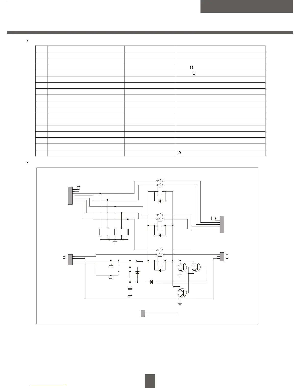
MAIN PARTS LIST OF THE AUXILIARY POWER AMPLIFYING BOARD
SCHEMATIC DIAGRAM OF THE AUXILIARY POWER AMPLIFYING BOARD
V302
S8050
VD303
1N4148
C301
330u/25V R308
20/2W
Y301
V301
9014
VD304
1N4148
Y302
VD305
1N4148
Y303
GSADC12V
C302
47u/25V
VD302
6.8V
R307
56k
1
2
3
4
5
6
7
XS4
7PIN
R306
4.7k
VD301
1N4148
SL
R
L
SR
C
GND
1
2
XP6
2PIN
GND
R301
100
R305
100
R304
100
R303
100
R302
100
XJ4
XJ6
1
2
3
4
5
6
7
XP5
7PIN
GND
C
SR
L
R
SL
1
2
3
4
XS7
4PIN
1
2
3
XS8
3PIN
V303
S8050
Vs
GND
From Sub-AMP Board
From Sub-AMP Board
To Output Board
To SW Speaker
GSA DC12V
GSADC12V


 To Next Page