T_o e TV's audio/video input jacks a_ lbr direct picture and
und connections between the TI, and a _,CB (or similar
device) that has audio/video output jacks. Both the AVI and AF2
Input Jack connections are shown on this"page, but either one can
be connected alone. Follow the ca@,steps below to connect ),our
accessory device to the AVI and AF2 in Jacks located on the back of
the TE
I
2
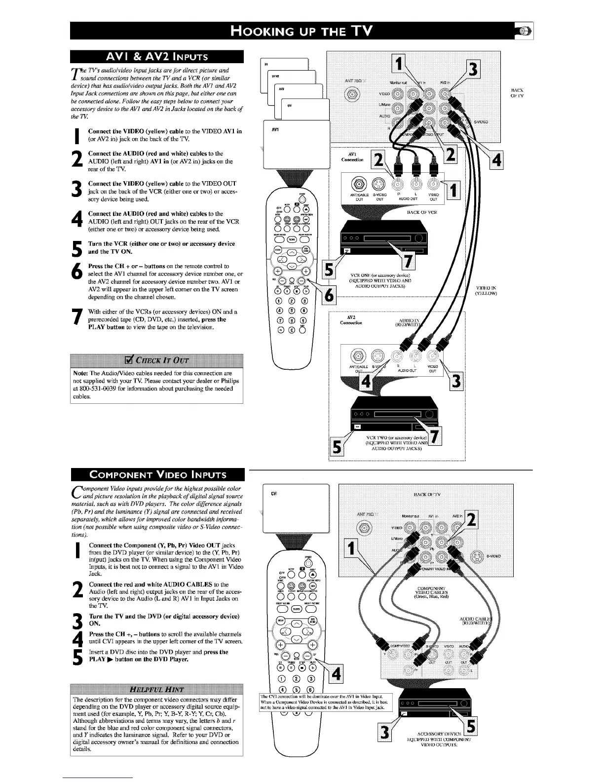
Connect the VIDEO (yellow) cable to the V_IDEO AVI in
(or AV2 in) jack on the back of die T%'.
Connect the AUDIO (red and white) cables to die
AUDIO (left and _ight) AVI in (or AV2 in) jacks on fire
rear of the T%'.
Connect the VIDEO (yellow) cable to the V_IDEO OUT
jack on the back of die VCR (eiflter one or two) or acces-
_wy device being used.
Connect the AUDIO (red and white) cables to die
AUDIO (left and _ight) OUT jacks on the _ear of the VCR
(either one or two) or aceessory device being used.
5
6
Turn the VCR (either one or two) or accessory device
and the TV ON.
Press the CH + or - buttons on the remote control m
select the AVI channel for accessory device number one, or
file AV2 channel for accessory device number two. AVI or
AV2 will appear in the upper left corner on the TV screen
depending tin the chrome] chosen.
With either of the VCRs (or accessory deviees) ON and a
prerecorded tape (CD, DVD, etc.) inserled, press the
PLAY button t_ view rite tape on rite _levision.
NNN
Note: The Audio!_rldeo cables needed for fltis connection are
not supplied wiflt your T_L Please contact your de*der or Philips
at 800-531-0039 for information about purchasing rite needed
cables.
@®@
®®®
(b®®
®®©
O];[W
AI30IO O_r[wt!'l JA(_iS)
L....................................................................................... •
Component I,_deo inputs provide for the highest possible color
and picture resolution in the playback of digital signal source
material, such as with DVD players. The color difference signals
(Pb, Pr) and the luminance (Y) signal are connected and received
separately, which allows ]br improved color bandwidth informa-
tion (not possible when using composite video or S4qdeo connec-
tions).
i Connect the Component (Y%Pb, Pr) Video OUT jacks
from fire DVD player (or similar device) to fire (y. Pb, Pr)
input) jacks on rite TV'. When ushtg the Compeneet Videx_
5tputs, it is best not to _xmnect a sigmtl to fire AV1 in Videx_
Jack.
Connect the red anti white AUDIO CABLES m theAudio (left mtd righ0 output jacks on the rear of the acees-
spry device t_ the Audio (L altd R) AV] in l!tput Jacks on
the T%'.
Turn the TV and file DVD (or digital accessory device)
ON.
Press the CH +, - buttons t_ scroll the available chantelsmttil CVI appears in the upper left comer of the T%r screen.
5tse_t a DVD disc into the DVD player and press the
PLAY I_ button on the DVD Player.
The description for the component video connectors may differ
depending on the DVD player or accessory digital source equip-
ment used (for ex_nple, Y, Pb, Pr; Y, B-Y, R-Y; _; Cr, C5).
Although abbreviations and ternls may vary, the lettc_ b and r
stand for fire blue and wedcolor component signal connectors,
and Y indicates fire luminance signal. Refer to your DVD or
digital accessory owner's manuM for definitions and connection
details.
CVI
iiiiiiiiiiiiiiiiiiiiiiiiiiiiiiiiiiiiiiiiiiiiiiiiiiiiiiiiiiiiiiiiiiiiiiiiiiiiiiiiiiiiiiiiiiiii
 Loading...