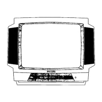
Do you have a question about the Philips 20PT6245/37 and is the answer not in the manual?
Provides a general overview of the television chassis layout and major sections.
Detailed schematic diagram for the power supply section of the TV.
Detailed schematic diagram for the deflection circuitry of the TV.
Detailed schematic diagram for the tuner and intermediate frequency (IF) stages.
Detailed schematic diagram for the video signal processing circuits.
Detailed schematic diagram for stereo and SAP audio processing.
Detailed schematic diagram for the mono audio amplifier and sound processing.
Schematic for front input/output, control panel, and headphone jack.
Schematic diagram detailing the rear input/output connections.
Schematic for the optional DVD power supply module.
Detailed schematic diagram for the Cathode Ray Tube (CRT) panel.
Top side component layout diagram for the mono carrier board.
Bottom side overview layout diagram for the mono carrier board.
Top side component layout diagram for the CRT panel.
Bottom side component layout diagram for the CRT panel.
Schematic diagram for the side jack panel connections.
Component layout diagram for the side jack panel.
Critical information regarding safe service operations and potential hazards.
Highlights critical components with special safety characteristics and potential hazards.
Mandatory safety checks to be performed after service to ensure safe operation.
Safety considerations related to fire and electrical shock during servicing.
Safety precautions regarding the picture tube implosion protection system.
Safety measures to prevent exposure to X-radiation from the picture tube.
Procedure for performing a cold leakage current test on the chassis.
Procedure for performing a hot leakage current test on the chassis.
Procedure and safety notes for using crimp type wire connectors.
Ensuring correct clearance distances for safety after component replacement.
Performing final leakage current tests to verify safety standards.
Step-by-step guide for removing the rear cover of the unit.
Instructions for placing the main panel in a service position.
Procedure for correctly mounting the rear cover after service.
Detailed explanation of the SDAM mode and its functions.
Instructions on how to access the Service Default Alignment Mode.
Guidance on resolving common picture quality issues through settings.
Guidance on resolving common sound issues through settings.
Prerequisites and conditions for performing alignments.
Procedures for hardware-specific alignment adjustments.
Detailed software-based alignments and settings for optimal performance.
Description of the audio signal processing stages.
Details on the audio amplifier circuit and its operation.
Explanation of the Automatic Volume Limiting function.
Information on the mute function and its conditions.
Overview of the switching mode power supply (SMPS) design.
Details on the various voltages supplied by the power supply unit.
Explanation of the Inter-Integrated Circuit (I2C) bus communication.
Description of the user interface functions and controls.
Control mechanisms for input and output signal selection.
How the microprocessor controls the power supply unit.
Overview of protection mechanisms managed by the microprocessor.
Physical location and identification of the CRT panel.
Physical location and identification of the side jack panel.
Physical location and identification of the top control panel.
Physical location and identification of the front interface panel.
Physical location and identification of the power supply module (A1).
Physical location and identification of the line deflection module (A2).
Physical location and identification of the tuner and IF module (A3).
Physical location and identification of the video processing module (A4).
Physical location and identification of the main chassis panel.
Physical location and identification of the audio processing module (A5).
Physical location and identification of the audio amplifier (A6).
Location of front I/O, control, and headphone connections (A7).
Physical location and identification of the rear I/O cinch connections (A8).
Physical location and identification of the optional DVD power supply (A9).
| Screen Size | 20 inches |
|---|---|
| Display Technology | CRT |
| Aspect Ratio | 4:3 |
| Tuner | Analog |
| Audio Output | Mono |
| Connectivity | RF input |
| Input Ports | RF input, Composite video input |





 Loading...