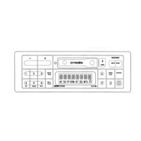
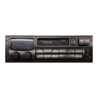
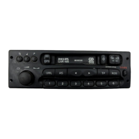
Cassette Car Radio
22DC594/35X
^" Televisieservice
Kttb
van de MORTEL"
Boksheuvelstraat 14
522 AV 's-HERTOGENBOSCH
Tel.:
(073)6218344
_
+
( )
O
[ O CITHOÊN O
[ 4
BAS
THE
®
BND
AST
MODE
(' 2 3)
BAS
THE
AF
TA
TP EDN
ST DD MTL
0
®
BND
AST
MODE
(4 5
i)
BAL
AF
TA
TP EDN
ST DD MTL
0
®
TA
AF
(§)
in • N D MT L
BAL
Bi
nCODE KDts
®
TA
AF
(§)
For repair information of the Cassette deck see Service
Manual No 4822 725 24637 of Auto Cassette Deck P6-29/3
Service Manual
Contents page
Controls
2
Connections 3
Technical Data - Cliips liandling
3a
Security code - Display test 4
IC91 module features 4a
Semiconductors - IC pinnings 5- 5a
Block Diagram 6- 6a
Connector block - Checks and alignments 7 - 7a
Front scliematic diagram 8- 8a
Front PWB layout
9
Startup - DC voltages 10
Microcontroller part schematic diagram 11 - 11a
Technician's remarks - Tuner part schematic diagram 12 - 12a
Main PWB layout 13 - 13a
Sound process part schematic diagram 14 - 14a
Power supply part schematic diagram 15 - 15a
Tape part schematic diagram 17 - 17a
Power amplifier part schematic diagram 18 - 18a
Exploded view 19 - 19a
Electrical partslist 20 -20a
12
Publishedby Philips Car Systems Printed in the Netherlands ® Copyright reserved Subject to moditication
4822 725 24384