Do you have a question about the Philips 32PFL3606H/58 and is the answer not in the manual?
Details about model numbers and their specifications.
Information on how to download user manuals and other product support.
Overview of input/output connectors on the TV set.
Overview of the TV chassis and its main components.
Safety guidelines for servicing the TV set to prevent hazards.
Important warnings regarding ESD, high voltage, and component handling.
General notes on measurements, schematic conventions, and component identification.
List of abbreviations used in the manual with their definitions.
Visual guide to cable routing within the TV for different models.
Recommended positions for servicing the TV to avoid damage.
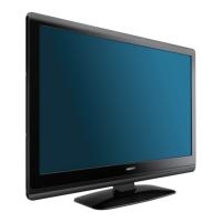
Step-by-step guide for disassembling the TV for the Thriller model.
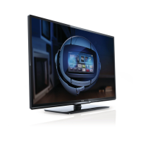
Step-by-step guide for disassembling the TV for the Berlinale model.
Instructions for reassembling the TV after repair in reverse order.
Key ICs for test pattern generation for fault diagnosis.
Explanation of Service Default Mode (SDM), Alignment Mode (SAM), and Customer Mode (CSM).
Diagram illustrating the TV's power state transitions.
Information on ComPair tool and additional cables for service.
Procedure for upgrading TV software via USB for product improvement.
Information on error codes stored in the NVM buffer for fault identification.
Method of error identification using LED blinking when OSD is not functional.
Tips for fault finding, NVM editing, and loading default values.
Conditions required for performing electrical adjustments and alignments.
Indicates that hardware alignments are not applicable for this model.
Procedure for software alignments like White Tone using SAM mode.
Information on microprocessor communication and option codes for ICs.
Steps to reset the NVM on a repaired SSB for correct TV operation.
Introduction to the TPM6.1E LA platform and its stylings.
Lists key components and ICs used in the chassis.
Overview of the TPM6.1E architecture with references to block diagrams.
Diagram showing the layout of components on the SSB for the Thriller model.
Diagram showing the layout of components on the SSB for the Berlinale model.
Description of the power supply unit and its output voltages.
Overview of power management and DC/DC converters for the Thriller model.
Description of system power input at connector CN7001 and test points.
Explanation of digital/analog power supply derived from +5V_SW.
Description of tuner power derivation from +12V.
Information about the 128 MB NAND flash used for software code.
Details about the System EEPROM containing NVM and adjustment data.
Description of the reset IC (U4007) and its function.
Description of the connector (CN4003) for control signals to the IR/LED/keyboard board.
Details about connectors CN4005 and CN4006 for iTV purposes.
Information about the service connector CN4008.
Description of the platform's audio amplifier IC (U6006) and its I2S interface.
Explanation of the mute circuit which is a DC drop detection circuit.
Explanation of the Audio Return Channel (ARC) feature on HDMI 1.
Description of the MT5135AE for DVB-T/C demodulation and CI+ controller.
Description of the tuner's capabilities including DVB-C, DVB-C, I2C control.
Function of IC U7008 in providing signals for panel control.
Role of IC U7010 in saving gamma and V-COM data for panels.
Description of the IC U7011 supporting the level shift function.
Internal block diagram and pin configuration of the MT5366CVGG IC.
Internal block diagram and pin configuration of the MT5135AE IC.
Internal block diagram of the TMDS251PAGR HDMI Switch IC.
Internal block diagram and pin configuration of the TPA6132A2RTER audio amplifier IC.
Internal block diagram and pin configuration of the STA339BWTR speaker amplifier IC.
Internal block diagram and pin configuration of the TPS54319 power supply IC.
Internal block diagram and pin configuration of the MAX17113ETL TCON/POWER IC.
Internal block diagram and pin configuration of the MAX9668ETP GAMMA IC.
Internal block diagram and pin configuration of the TPS65192RHDR IC.
Internal block diagram and pin configuration of the MAX17119ETI+T IC.
Internal block diagram and pin configuration of the TMDS351PAG HDMI Switch IC.
Wiring diagram showing connections for the Thriller 32" model.
Wiring diagram showing connections for the Thriller 42" model.
Wiring diagram showing connections for the Berlinale 32" model.
Block diagram illustrating the system architecture for the Thriller model.
Block diagram illustrating the system architecture for Berlinale xxPFL5606 model.
Block diagram illustrating the system architecture for Berlinale xxPFL5406 model.
Circuit diagram and PWB layout for the PSU Adapter (A01) of Thriller 32".
Circuit diagram and PWB layout for the Inverter (A02) of Thriller 32".
Circuit diagram and PWB layout for the PSU Adapter (A01) of Thriller 42".
Circuit diagram and PWB layout for the Inverter (A02) of Thriller 42".
Circuit diagram and PWB layout for the PSU Adapter (A01) of Berlinale.
Circuit diagram and PWB layout for the LED board (A02) of Berlinale.
Circuit diagram for System Power 1 (B01) of SSB Thriller.
Circuit diagram for System Power 2 (B02) of SSB Thriller.
Schematic diagrams for various peripheral circuits like NAND Flash, EEPROM, Reset IC.
Circuit diagrams for connectors, USB port, and RS232 interface.
Circuit diagrams for Audio I/O, SPDIF output, and headphone circuits.
Circuit diagrams for the speaker amplifier and mute circuit.
Circuit diagrams for video inputs (YPbPr) and SPDIF output.
Circuit diagrams for SCART connector functions including RGB, CVBS, and audio.
Circuit diagrams for VGA input, sync slicer, EDID, and audio.
Circuit diagrams for LVDS output, analog power, and bright adjust.
Schematics for DDR2 DRAM interface and related damping/termination circuits.
Schematics for MII, GPIO, and ServAD interfaces.
Circuit diagrams for HDMI switch, ESD protection, and ARC functionality.
Circuit diagrams for the DVB T/C demodulator and CI interface.
Circuit diagrams for the tuner, I2C, RF AGC, and DIF functions.
Circuit diagrams for TCON, Power Block, and GAMMA circuits.
Circuit diagram for System Power 1 of SSB Berlinale.
Circuit diagram for System Power 2.
Schematics for peripheral circuits including NAND Flash and EEPROM.
Circuit diagrams for USB, RS232, and other connectors.
Circuit diagrams for audio I/O, SPDIF, and headphone sections.
Circuit diagrams for speaker amplification and mute control.
Circuit diagrams for YPbPr video input and analog audio input.
Circuit diagrams for SCART input/output and related control signals.
Circuit diagrams for VGA input, sync slicer, EDID, and audio.
Circuit diagrams for LVDS interface, analog power, and backlight control.
Schematics for DDR2 DRAM interface and damping/termination circuits.
Schematics for MII, GPIO, and ServAD interfaces.
Circuit diagrams for HDMI switch, ESD protection, and ARC functionality.
Circuit diagrams for the DVB T/C demodulator and CI interface.
Circuit diagrams for the tuner, I2C, RF AGC, and DIF functions.
Circuit diagrams for TCON, Power Block, and GAMMA circuits.
Circuit diagram for System Power 1 of SSB Berlinale.
Circuit diagram for the IR/LED board of the Thriller model.
Circuit diagram for the IR/LED board of the Berlinale model.
Exploded view and parts list for the Thriller 32" model.
Exploded view and parts list for the Thriller 42" model.
Exploded view and parts list for the Berlinale 32" model.
| Screen Size | 32 inches |
|---|---|
| Resolution | 1366 x 768 pixels |
| Display Type | LCD |
| HD Type | HD Ready |
| HDMI Ports | 2 |
| USB Ports | 1 |
| Audio Output | 2x 10W |
| Contrast ratio (typical) | 1000:1 |
| Response time | 8 ms |
| Brightness | 300 cd/m² |
| Component video (YPbPr/YCbCr) in | 1 |
| SCART ports quantity | 1 |
| Common interface (CI) | Yes |
| RMS rated power | 20 W |
| Number of speakers | 2 |
| Refresh Rate | 60 Hz |
| Smart TV | No |
| Built-in Wi-Fi | No |
| Energy Efficiency Class | A |
| USB 2.0 ports quantity | 1 |
| Screen format adjustments | 4:3, 16:9, Zoom, Auto |
| Supported video modes | 480i, 480p, 576i, 576p, 720p, 1080i, 1080p |
| Teletext | 1000 pages |





 Loading...