4
TPT1.1A LA
1. Technical Specifications, Connections and Chassis Overview
B. CVBS
The input signals are applied to display through CVBS cable
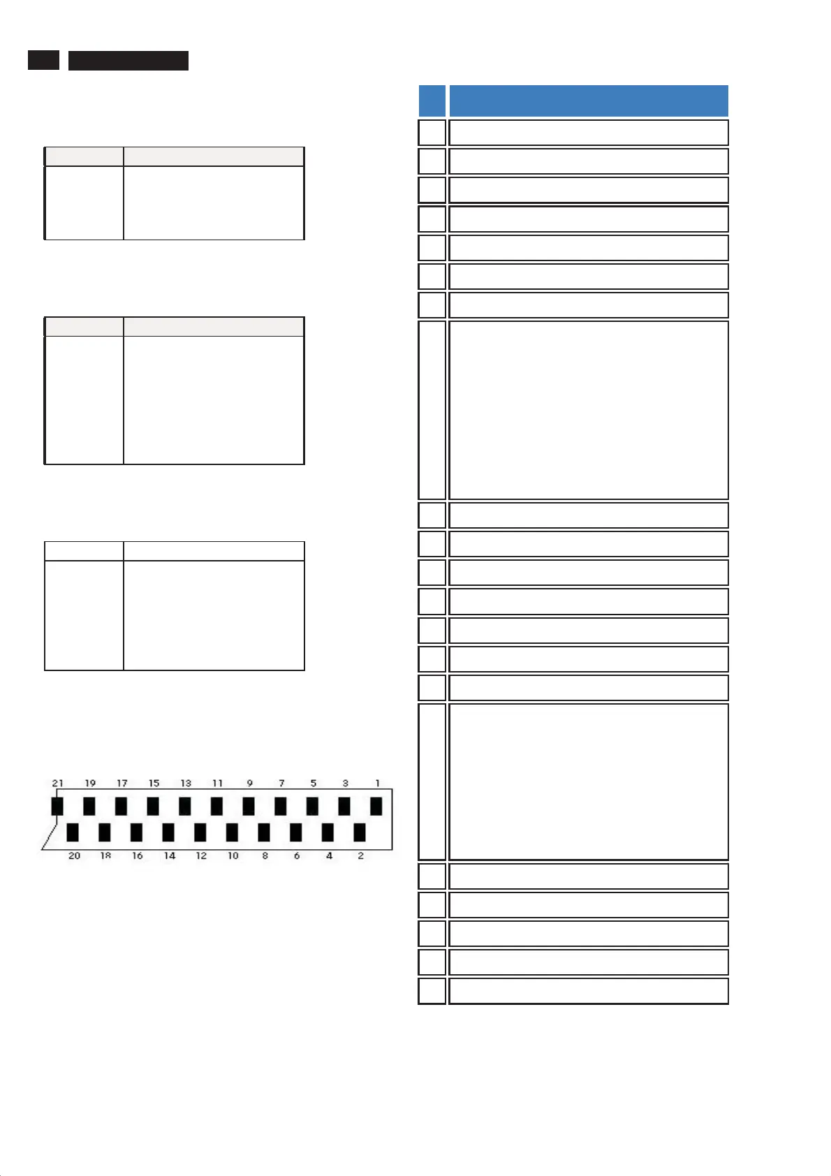
Pin assignment
PIN NO. SIGNAL
1GND
2 CVBS
3 CVBS
4 CVBS
C. S-Video
The input signals are applied to display through S-Video cable
Pin assignment
PIN NO. SIGNAL
1GND
2GND
3GND
4GND
5GND
6LUMA
8CHROMA
D. Component Video
The input signals are applied to display through Component Video
RCA Jack pin assignment
PIN NO. SIGNAL
1GND
2Redà Pr
3GND
4Blueà Pb
5GND
6GreenàY
E. SCART
Scart connector is only u sed in WE model. The Scart (Syndicat
des Constructeurs d'Appareils Radiorécepteurs et Téléviseurs)
connector is used for combined audio and video connections.
Pin TV SCART
1 N/C
2 Right audio input
3 N/C
4 Audio ground
5 Blue ground
6 Left audio input
7 Blue output
8
0-2.5 v olts (low) when:
TV output
4.5-7.5 v olts (High-t o-6v) when:
-inputting picture format setting is '16:9',
9-12 volts (high-to-12v) when:
-inputing picture format setting is '4:3'
9 Green ground
10 N/C
11 Green output
12 N/C
13 Red ground
14 N/C
15 Red output
16
0 volt (low) when:- pin 8 of the TV scart is low
or when:
- Composite video signal
1-3 vol ts (high) when:
- video input setting is 'RGB',
17 Composite video output ground
18 Composite video input ground
19 N/C
20 Composite video input
21 Ground