4
TPT1.2A LA
1. Technical Specifications, Connections and Chassis Overview
PIN
No.
SIGNAL b(PC)
1Red
2Green
3Blue
4NC
5GND
6RedGND
7GreenGND
8BlueGND
9 +5V (Supply from PC)
10 Sync GND
11 NC
12 SDA
13 H-sync
14 V-sync
15 SCL
No. 1
No. 2
No. 19
No. 18
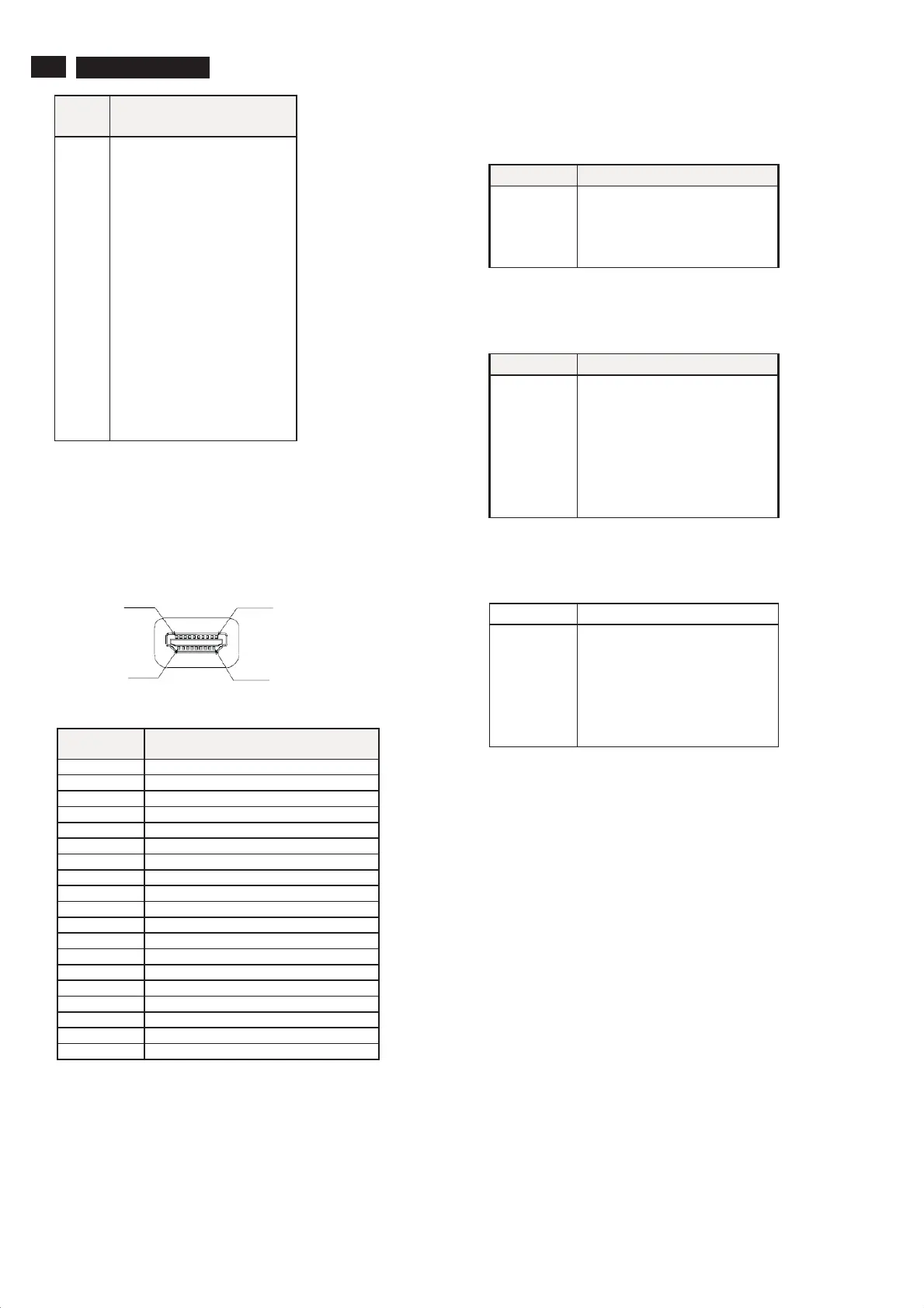
Type A Connector
PIN
No.
SIGNAL
1 TMDS Data2+
2 TMDS Data2 shield
3 TDMS Data2-
4 TMDS Data1+
5 TMDS Data1 shield
6 TMDS Data1-
7 TMDS Data0+
8 TMDS Data0 shield
9 TMDS Data0-
10 TMDS Clock+
11 TMDS Clock Shield
12 TMDS Clock-
13 CEC
14 Reserved (N.C. on device)
15 SCL
16 SDA
17 DDC/CEC Ground
18 +5V Power
19 Hot Plug Detect
TV video input /output connectors
A. HDMI for digital Video / Audio interface with pin assignment
as follows:
B. CVBS
The input signals are applied to display through CVBS cable
Pin assignment
PIN NO. SIGNAL
1GND
2 CVBS
3 CVBS
4 CVBS
C. S-Video
The input signals are applied to display through S-Video cable
Pin assignment
PIN NO. SIGNAL
1GND
2GND
3GND
4GND
5GND
6LUMA
8 CHROMA
D. Component Video
The input signals are applied to display through Co mponent Video
RCA Jack pin assignment
PIN NO. SIGNAL
1GND
2Redà Pr
3GND
4Blueà Pb
5GND
6GreenàY