EasyManua.ls Logo

Philips 48PFT5500/12 User Manual

Philips 48PFT5500/12
145 pages
To Next Page IconTo Next Page
Page #1 background imageLoading...
Page #1 background image
Published by CQZ/SC 1540 Quality Printed in the Netherlands Subject to modification EN 3122 785 19886
2015-Sep-30
2015
©
TP Vision Netherlands B.V.
All rights reserved. Specifications are subject to change without notice. Trademarks are the
property of Koninklijke Philips Electronics N.V. or their respective owners.
TP Vision Netherlands B.V. reserves the right to change products at any time without being obliged to adjust
earlier supplies accordingly.
PHILIPS and the PHILIPS’ Shield Emblem are used under license from Koninklijke Philips Electronics N.V.
Colour Television Chassis
QM15.2E
LA
Contents Page Contents Page
1. Revision List 2
2. Technical Specs, Diversity, and Connections 2
3. Precautions, Notes, and Abbreviation List 7
4. Mechanical Instructions 11
Cable dressing (32" 5500 series) 11
Cable dressing (32" 6500 series) 12
Cable dressing (39" 5500 series) 12
Cable dressing (40" 5500 series) 13
Cable dressing (40" 6400 series) 13
Cable dressing (40" 6510&6540 series) 14
Cable dressing (40" 6550&6560&6580 series) 14
Cable dressing (48" 5500 series) 15
Cable dressing (50" 6400 series) 15
Cable dressing (50" 6510&6540 series) 16
Cable dressing (50" 6550&6560&6580 series) 16
Cable dressing (55" 5500&6400 series) 17
Cable dressing (55" 6510&6540 series) 17
Cable dressing (55" 6550&6560&6580 series) 18
Cable dressing (65" 6520 series) 18
5. Service Modes, Error Codes, and Fault Finding 29
6. Alignments 38
7. Circuit Descriptions 42
8. IC Data Sheets 48
9. Block Diagrams
Block diagram 5500/65x0/6400 series 55
10. Circuit Diagrams and PWB Layouts Drawing PWB
A 715G6934 PSU
56 58-59
A 715G6679 PSU 60 64-65
A 715G6973 PSU 66 70-71
A 715G6677 PSU 72 76-77
A 715G6960 PSU 78 82-83
B 715G7030 SSB 84 99-100
J 715G7074 IR/LED Panel 101 102
E 715G7088 Keyboard control panel 105 106
E 715G7118 Keyboard control panel 107 108
AL 715G7035 Ambilight Board 109 111
AL 715G7036 Amiblight Board 112 113
AL 715G6981 Ambilight Board 114 116
AL 715G7004 Ambilight Board 117 119
AL 715G7006 Ambilight Board 120 122
AL 715G7007 Ambilight Board 123 125
AL 715G7037 Ambilight Board 126 128
AL 715G7038 Amiblight Board 129 130
11. Styling Sheets
5500 series 32" 131
6500 series 32" 132
5500 series 39" 133
5500 series 40" 134
6400 series 40" 135
6510&6540 series 40" 136
6550&6560&6580 series 40" 137
5500 series 48" 138
6400 series 50" 139
6510&6540 series 50" 140
6550&6560&6580 series 50" 141
5500&6400 series 55" 142
6510&6540 series 55" 143
6550&6560&6580 series 55" 144
6520 series 65" 145

Table of Contents

Question and Answer IconNeed help?

Do you have a question about the Philips 48PFT5500/12 and is the answer not in the manual?

Philips 48PFT5500/12 Specifications

General IconGeneral
BrandPhilips
Model48PFT5500/12
CategoryTV
LanguageEnglish

Summary

2. Technical Specs, Diversity, and Connections

2.1 Technical Specifications

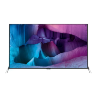
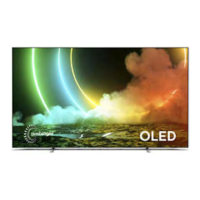
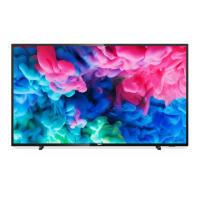
Provides detailed technical specifications for the television model, including performance metrics and features.

3. Precautions, Notes, and Abbreviation List

3.1 Safety Instructions

Crucial safety guidelines and precautions to be followed during repair to prevent electrical hazards and damage.

3.2 Warnings

Important warnings regarding electrostatic discharge (ESD), high voltage, and component replacement procedures.

4. Mechanical Instructions

4.3 Assembly/Panel Removal (for 32"/39"/40"/55"Pxx5500 series & 40"/50"/55"Pxx6400 series)

Step-by-step instructions for disassembling and removing panels for specific 5500 and 6400 series models.

4.4 Assembly/Panel Removal (for 32"/40"/50"/55"Pxx65x0 series)

Step-by-step instructions for disassembling and removing panels for specific 65x0 series models.

4.5 Assembly/Panel Removal (for 65"PFx6520 series)

Detailed instructions for disassembly and panel removal specifically for 65" PFx6520 series models.

5. Service Modes, Error Codes, and Fault Finding

5.2 Service Modes

Details various service modes (SDM, SAM, Factory, CSM, ComPair) and their purposes for repair and alignment.

5.5 Software Upgrading

Provides instructions on how to upgrade the TV's main software using a USB port and memory stick.

5.6 Error Codes

Explains how TV errors are indicated, stored in an error buffer, and how to read them.

5.7 The Blinking LED Procedure

Describes how the front LED blinks to indicate specific errors, useful when the OSD is not working.

5.8 Fault Finding and Repair Tips

Offers general advice and specific tips for troubleshooting common issues like no picture or unstable HDMI input.

6. Alignments

6.3 Software Alignments

Guides through software alignments, including White Point and Display adjustments using SAM mode.

6.5 Reset of Repaired SSB

Details the critical steps for resetting the SSB's NVM and programming type number and production code after repair.

7. Circuit Descriptions

7.2 Power Supply

Describes the power supply architecture, key components, and output voltages for different models.

10. Circuit Diagrams and PWB Layouts

10.1 Power Supply Units (PSU)

Circuit diagrams and PWB layouts for various PSU models (A715G6934, A715G6679, A715G6973, A715G6677, A715G6960).

10.4 Main Signal Boards (SSB)

Circuit diagrams for the main signal boards (SSB), covering system power, peripheral, DDR3, and audio/video interfaces.

10.6 Ambilight Boards

Circuit diagrams and layouts for various Ambilight boards (TCL5971, 715G7035, 715G7036, 715G6981, 715G7004, 715G7007).

Related product manuals