EasyManua.ls Logo

Philips 55PUT6400/12 User Manual

Philips 55PUT6400/12
145 pages
To Next Page IconTo Next Page
Page #1 background imageLoading...
Page #1 background image
Published by CQZ/SC 1540 Quality Printed in the Netherlands Subject to modification EN 3122 785 19886
2015-Sep-30
2015
©
TP Vision Netherlands B.V.
All rights reserved. Specifications are subject to change without notice. Trademarks are the
property of Koninklijke Philips Electronics N.V. or their respective owners.
TP Vision Netherlands B.V. reserves the right to change products at any time without being obliged to adjust
earlier supplies accordingly.
PHILIPS and the PHILIPS’ Shield Emblem are used under license from Koninklijke Philips Electronics N.V.
Colour Television Chassis
QM15.2E
LA
Contents Page Contents Page
1. Revision List 2
2. Technical Specs, Diversity, and Connections 2
3. Precautions, Notes, and Abbreviation List 7
4. Mechanical Instructions 11
Cable dressing (32" 5500 series) 11
Cable dressing (32" 6500 series) 12
Cable dressing (39" 5500 series) 12
Cable dressing (40" 5500 series) 13
Cable dressing (40" 6400 series) 13
Cable dressing (40" 6510&6540 series) 14
Cable dressing (40" 6550&6560&6580 series) 14
Cable dressing (48" 5500 series) 15
Cable dressing (50" 6400 series) 15
Cable dressing (50" 6510&6540 series) 16
Cable dressing (50" 6550&6560&6580 series) 16
Cable dressing (55" 5500&6400 series) 17
Cable dressing (55" 6510&6540 series) 17
Cable dressing (55" 6550&6560&6580 series) 18
Cable dressing (65" 6520 series) 18
5. Service Modes, Error Codes, and Fault Finding 29
6. Alignments 38
7. Circuit Descriptions 42
8. IC Data Sheets 48
9. Block Diagrams
Block diagram 5500/65x0/6400 series 55
10. Circuit Diagrams and PWB Layouts Drawing PWB
A 715G6934 PSU
56 58-59
A 715G6679 PSU 60 64-65
A 715G6973 PSU 66 70-71
A 715G6677 PSU 72 76-77
A 715G6960 PSU 78 82-83
B 715G7030 SSB 84 99-100
J 715G7074 IR/LED Panel 101 102
E 715G7088 Keyboard control panel 105 106
E 715G7118 Keyboard control panel 107 108
AL 715G7035 Ambilight Board 109 111
AL 715G7036 Amiblight Board 112 113
AL 715G6981 Ambilight Board 114 116
AL 715G7004 Ambilight Board 117 119
AL 715G7006 Ambilight Board 120 122
AL 715G7007 Ambilight Board 123 125
AL 715G7037 Ambilight Board 126 128
AL 715G7038 Amiblight Board 129 130
11. Styling Sheets
5500 series 32" 131
6500 series 32" 132
5500 series 39" 133
5500 series 40" 134
6400 series 40" 135
6510&6540 series 40" 136
6550&6560&6580 series 40" 137
5500 series 48" 138
6400 series 50" 139
6510&6540 series 50" 140
6550&6560&6580 series 50" 141
5500&6400 series 55" 142
6510&6540 series 55" 143
6550&6560&6580 series 55" 144
6520 series 65" 145

Table of Contents

Question and Answer IconNeed help?

Do you have a question about the Philips 55PUT6400/12 and is the answer not in the manual?

Philips 55PUT6400/12 Specifications

General IconGeneral
Screen Size55 inches
Resolution4K Ultra HD (3840 x 2160)
Display TechnologyLED
Smart TVYes
Audio Output20 W
HDMI Ports4
USB Ports2
Refresh Rate60 Hz
Operating SystemSAPHI
Wi-FiYes
BluetoothNo
EthernetYes
HDRYes

Summary

Technical Specifications and Connections

2.1 Technical Specifications

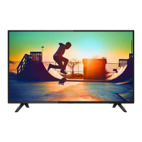
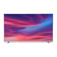
Details on product specifications, support links, and model diversity.

Precautions, Notes, and Abbreviations

3.1 Safety Instructions

Essential safety regulations to follow during and after repair procedures.

3.2 Warnings

Important warnings regarding ESD, high voltage, and component replacement.

Mechanical Instructions

4.3 Assembly and Panel Removal (Pxx5500/Pxx6400 series)

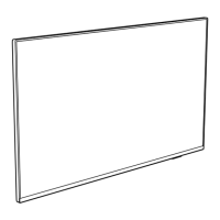
Step-by-step guide for disassembling specific models, including rear cover and SSB removal.

4.4 Assembly and Panel Removal (Pxx65x0 series)

Step-by-step guide for disassembling Pxx65x0 series models, including rear cover and SSB removal.

4.5 Assembly and Panel Removal (PFx6520 series)

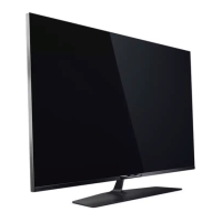
Step-by-step guide for disassembling PFx6520 series models, including stand and rear cover removal.

Service Modes, Error Codes, and Fault Finding

5.2 Service Modes

Overview of different service modes and their functions for repair and alignment.

5.6 Error Codes and Buffer

Explanation of error codes, their storage, and how to read the error buffer.

5.7 The Blinking LED Procedure

Procedure for identifying errors using front LED blinking patterns.

5.8 Fault Finding and Repair Tips

General tips for fault finding, NVM editing, and specific troubleshooting scenarios.

Alignments

6.3 Software Alignments

Procedure for aligning white point and display settings using Service Alignment Mode (SAM).

6.5 Reset of Repaired SSB

Procedure for resetting NVM on a repaired SSB, including type number and production code.

Circuit Descriptions

7.2 Power Supply

Description of the power supply architecture, control signals, and output voltages.

Block Diagrams

Circuit Diagrams and PWB Layouts

Related product manuals