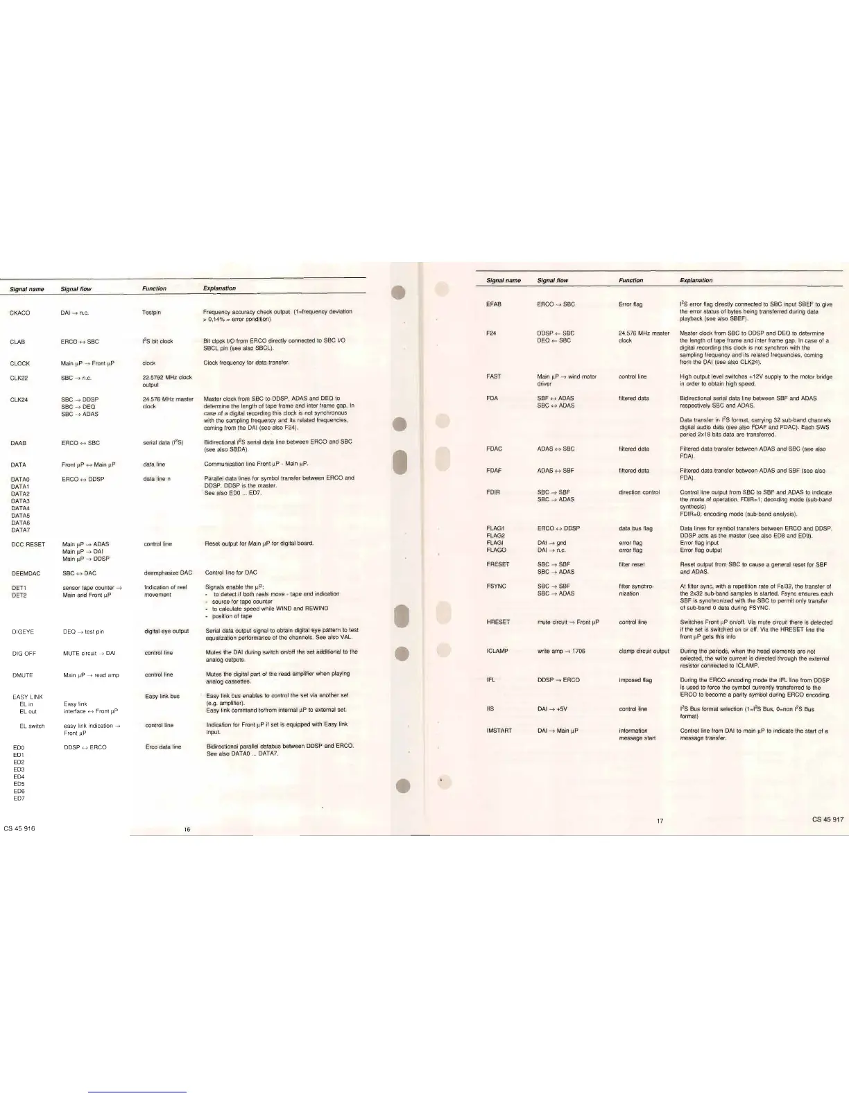
Signal name Signal flow Function Explanation
Signal name
Signal flow
Function
Explanation
EFAB ERCO
-->
SBC Error flag
1
2
S error flag directly connected
to
SBC input SBEF
to
give
CKACO
DAI
-->
n.C.
Testpin
Frequency accuracy check output.
(1
=frequency deviation
the error status of bytes being transferred during data
> 0,14% = error condition)
playback (see also SBEF).
F24 DDSP
<- SBC 24.576 MHz master
Master clock from SBC
to
DDSP and DEQ
to
determine
CLAB
ERCO H SBC
1
2
S bit clock
Bit clock I/O from ERCO directly connected to SBC I/O
DEQ
<- SBC clock the length of tape frame and inter frame gap.
In
case of a
SBCL pin (see also SBCL).
digital recording this clock
is
not synchron with the
sampling frequency and its related frequencies, coming
CLOCK Main
~P
-->
Front
~P
clock
Clock frequency for data transfer.
from the
DAI
(see also CLK24).
CLK22
SBC
-->
n.C.
22.5792 MHz clock
FAST
Main
~P
-->
wind motor
control line High output level switches +12V supply
to
the motor bridge
output
driver
in
order
to
obtain high speed.
CLK24
SBC
-->
DDSP
24.576 MHz master
Master clock from SBC to DDSP, ADAS and DEQ to
FDA SBF
H ADAS filtered data Bidirectional serial data line between SBF and ADAS
SBC
-->
DEQ
clock
determine the length of tape frame and inter frame gap.
In
SBC H ADAS respectively SBC and ADAS.
SBC
-->
ADAS
case of a digital recording this clock
is
not synchronous
with the sampling frequency and its related frequencies,
Data transfer
in
1
2
S format, carrying
32
sub-band channels
coming from the DAI (see also F24).
digital audio data (see also FDAF and FDAC). Each SWS
period 2x18 bits data are transferred.
DAAB
ERCO
H SBC
serial data
(1
2
S)
Bidirectional 1
2
S serial data line between ERCO and SBC
(see also SBDA).
FDAC
ADAS
H SBC filtered data Filtered data transfer between ADAS and SBC (see also
FDA).
DATA
Front
~P
H Main
~P
data line
Communication line Front
~P
- Main
~P.
FDAF ADAS H SBF filtered data Filtered data transfer between ADAS and SBF (see also
DATAO
ERCO H DDSP
data line n
Parallel data lines for symbol transfer between ERCO and
FDA).
DATA1
DDSP. DDSP
is
the master.
DATA2
See also
EDO
..
ED7.
FDIR
SBC
-->
SBF direction control Control line output from SBC to SBF and ADAS
to
indicate
DATA3
SBC
-->
ADAS the mode of operation. FDIR=1; decoding mode (sub-band
DATA4
synthesis)
DATA5
FDIR=O;
encoding mode (sub-band analysis).
DATA6
DATA7
FLAG1
ERCO H DDSP data bus flag Data lines for symbol transfers between ERCO and DDSP.
FLAG2
DDSP acts as the master (see also ED8 and ED9).
DCC RESET
Main
~P
-->
ADAS
control line
Reset output for Main
~P
for digital board.
FLAGI
DAI
-->
gnd error flag Error flag input
Main
~P
-->
DAI
FLAGO
DAI
-->
n.c. error flag Error flag output
Main
~
P
-->
DDSP
FRESET SBC
-->
SBF filter reset Reset output from SBC
to
cause a general reset for SBF
DEEMDAC
SBC
H DAC
deemphasize DAC
Control line for DAC
SBC
-->
ADAS and ADAS.
DEn
sensor tape counter
-->
Indication of reel
Signals enable the
~P:
FSYNC SBC
-->
SBF filter synchro- At filter sync, with a repetition rate of Fs/32, the transfer of
DET2
Main and Front
~P
movement
to
detect if both reels move - tape end indication
SBC
-->
ADAS nization the 2x32 sub-band samples
is
started. Fsync ensures each
source for tape counter
SBF
is
synchronized with the SBC to permit only transfer
to calculate speed while WIND and REWIND
of sub-band 0 data during FSYNC.
position of tape
HRESET
mute circuit
-->
Front
~P
control line
Switches Front
~P
on/off. Via mute circuit there
is
detected
DIGEYE DEQ
-->
test pin
digital eye output
Serial data output signal
to
obtain digital eye pattern to test
if the set
is
switched
on
or off. Via the HRESET line the
equalization performance of the channels. See also VAL.
front
~P
gets this info
DIG OFF
MUTE circuit
-->
DAI
control line
Mutes the
DAI
during switch on/off the set additional to the
ICLAMP
write amp
-->
1706 clamp circuit output During the periods, when the head elements are not
analog outputs.
selected, the write current
is
directed through the external
resistor connected to ICLAMP.
DMUTE
Main
~P
-->
read amp
control line
Mutes the digital part of the read amplifier when playing
analog cassettes.
IFL
DDSP
-->
ERCO imposed flag During the ERCO encoding mode the IFL line from DDSP
is
used to force the symbol currently transferred to the
EASY LINK
Easy link bus
Easy link bus enables to control the set via another set
ERCO to become a parity symbol during ERCO encoding.
EL
in
Easy link
(e.g. amplifier).
EL out
interface
H Front
~P
Easy link command to/from internal
~P
to
ex1ernal
set.
liS
DAI
-->
+5V
control line
1
2
S Bus format selection
(1
=1
2
S Bus,
O=non
1
2
S Bus
format)
EL switch
easy link indication
-->
control line
Indication for Front
~P
if set
is
equipped with Easy link
Front
~P
input.
IMSTART
DAI
-->
Main
~P
information
Control line from
DAI
to main
~P
to
indicate the start of a
message start message transfer.
EDO
DDSP H ERCO
Erco data line
Bidirectional parallel databus between DDSP and ERCO.
ED1
See also
DATAO
...
DATA7.
ED2
ED3
ED4
ED5
ED6
ED7
CS
45
916
16
17
CS
45
917
 Loading...