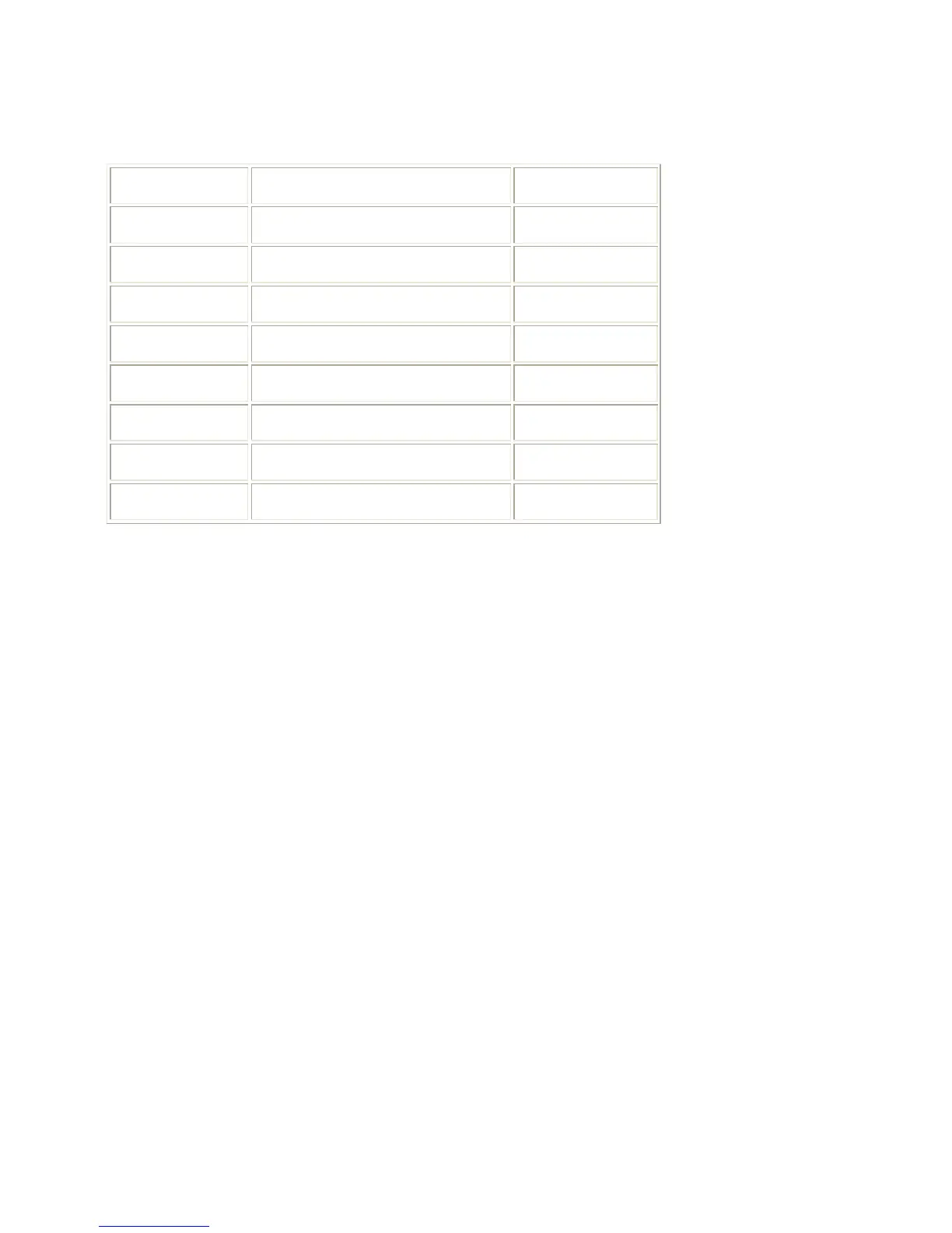
Table: Test Point Overview
Test point Circuit Diagram
A1-A2-A3-.. Audio processing A8, A9 / A11
C1-C2-C3-.. Control A7
F1-F2-F3-.. Frame drive and output A3
I1-I2-I3-.. Tuner & IF A4
L1-L2-L3-. Line drive and output A2
P1-P2-P3-.. Power supply A1
S1-S2-S3-.. Synchronization A6
V1-V2-V3-.. Video processing A5, B1
The numbering is in a logical sequence for diagnostics. Always start diagnosing within a
functional block in the sequence of the relevant test points for that block.
Perform measurements under the following conditions:
• Television set in Service Default Alignment Mode.
• Video input: Color bar signal.
• Audio input: 3 kHz left channel, 1 kHz right channel.