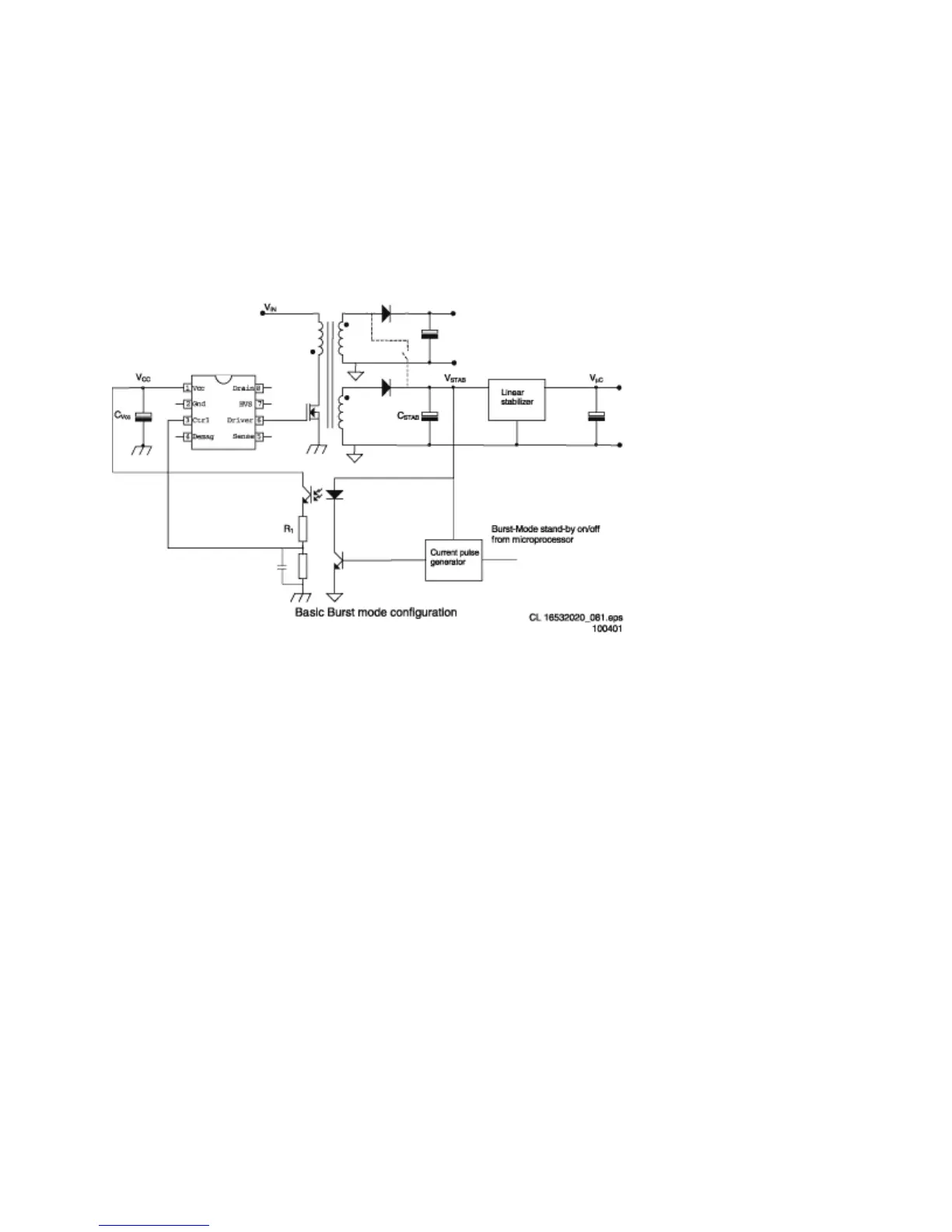
In the active period the energy is transferred to the secondary and stored in the buffer
capacitor C
STAB
in front of the linear stabilizer (see Figure below). During the inactive
period, the load (e.g. microprocessor) discharges this capacitor. In this mode, the
controller makes use of the Safe-Restart mode.
Figure:
The system enters burst mode standby when the microprocessor activates the
‘Stdby_con’ line. When this line is pulled high, the base of Q7541 is allowed to go high.
This is triggered by the current from collector Q7542. When Q7541 turns ‘on’, the opto-
coupler (7515) is activated, sending a large current signal to pin 3 (Ctrl). In response to
this signal, the IC stops switching and enters a ‘hiccup’ mode. This burst activation
signal should be present for longer than the ‘burst blank’ period (typically 30 µs): the
blanking time prevents false burst triggering due to spikes.
Burst mode standby operation continues until the microcontroller pulls the ‘Stdby_con’
signal low again. The base of Q7541 is unable to go high, thus cannot turn ‘on’. This will
disable the burst mode. The system then enters the start-up sequence and begins
normal switching behavior.