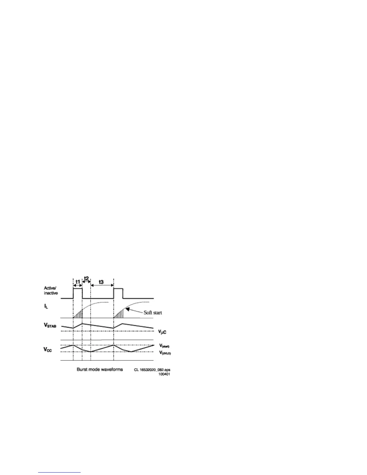
For a more detailed description of one burst cycle, three time intervals are defined:
• t1: Discharge of V
CC
when gate drive is active During the first interval, energy is
transferred, which result in a ramp-up of the output voltage (V
STAB
) in front of the
stabilizer. When enough energy is stored in the capacitor, the IC will be switched
‘off’ by a current pulse generated at the secondary side. This pulse is transferred
to the primary side via the opto coupler. The controller will disable the output
driver (safe restart mode) when the current pulse reaches a threshold level of 16
mA into the Ctrl pin. A resistor R
1
(R3519) is placed in series with the opto
coupler, to limit the current going into the Ctrl pin. Meanwhile the V
CC
capacitor is
discharged but has to stay above V
UVLO
.
• t2: Discharge of V
CC
when gate drive is inactive During the second interval, the
V
CC
is discharged to V
UVLO
.The output voltage will decrease depending on the
load.
• t3: Charge of V
CC
when gate drive is inactive The third interval starts when the
UVLO is reached. The internal current source charges the V
CC
capacitor (also
the soft start capacitor is recharged). Once the V
CC
capacitor is charged to the
start-up voltage, the driver is activated and a new burst cycle is started.
Figure: