5-1 5-1
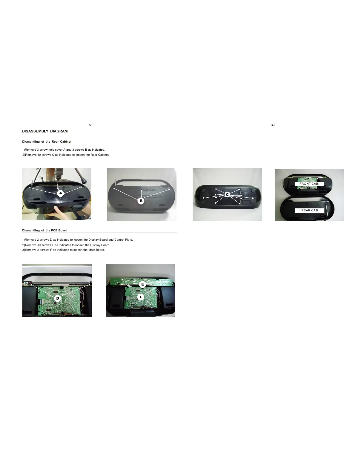
DISASSEMBLY DIAGRAM
Dismantling of the Rear Cabinet
Dismantling of the PCB Board
1)Remove 2 screws D as indicated to loosen the Display Board and Control Plate.
2)Remove 10 screws E as indicated to loosen the Display Board.
3)Remove 2 screws F as indicated to loosen the Main Board.
1)Remove 3 screw hole cover A and 3 screws B as indicated.
2)Remove 10 screws C as indicated to loosen the Rear Cabinet.
A
B
C
D
E
F
FRONT CAB.
REAR CAB.