Service modes, repair tips and faultfinding trees
GB 28 CDR 3rd gen.5.
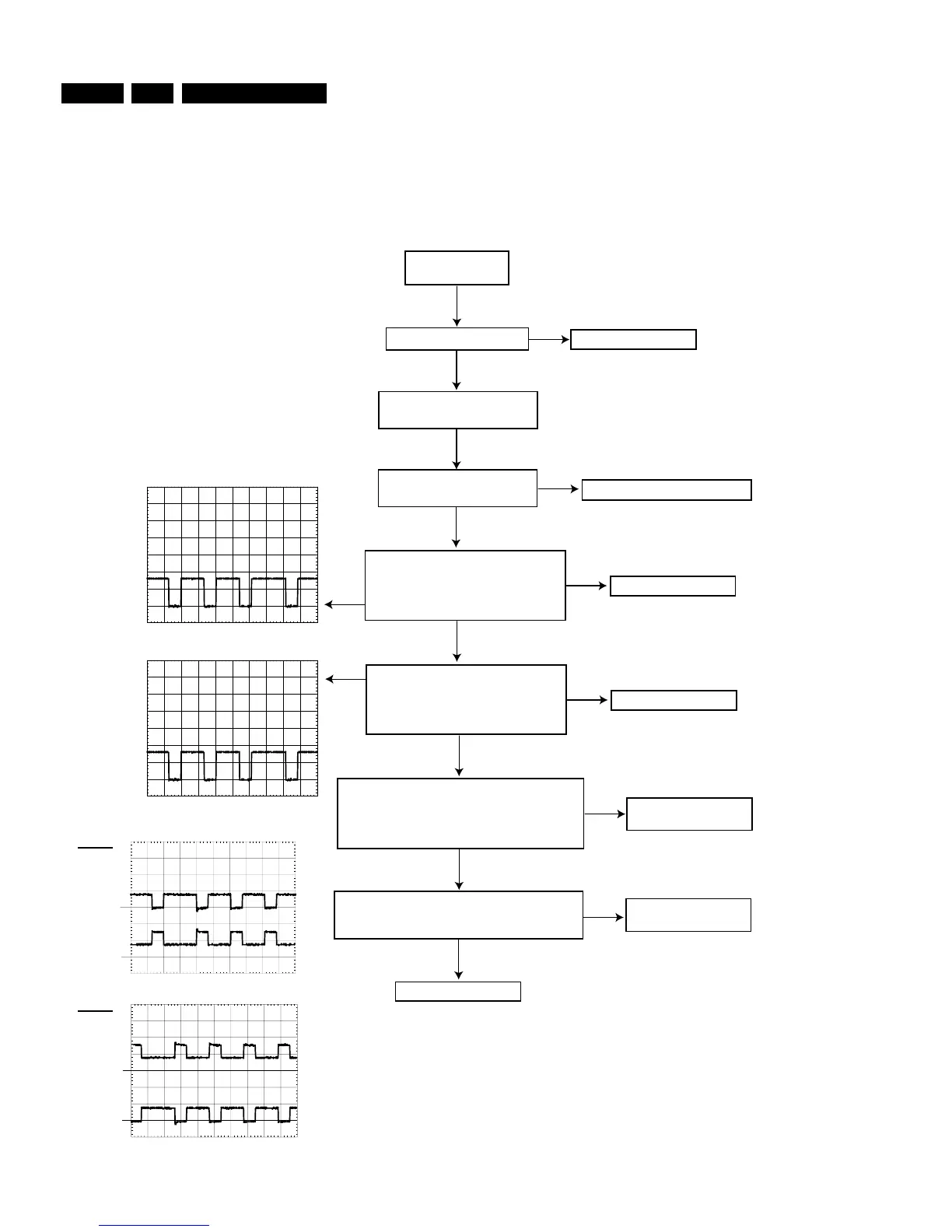
Figure 5-18
NOK
OK
OK
TRAY SERVO OK
Switch on player
in MDD mode
SERVO DRIVERS CHECK
USE CDR MAIN BOARD CIRCUIT DIAGRAMS 3 AND 4 AND CDR MAIN BOARD BOTTOM VIEW : SERVO DRIVERS TESTPOINTS
Execute "TRAY" tests
Check power part
Check reset and clock part
Check
S1V65
(=1V65) at
testpoint S9
NOK
Check IC7215, T7201, T7202
OK
Check MACE 7270
Check signal
TRAYSW
at testpoint S23 :
3V3 during commands open and close,
0V after completion
Check driver 7240
Check CDL4009
OK
TRAY SERVO OK
TRAY SERVO
OK
NOK
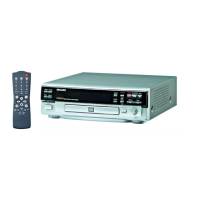
PM3392A
CH1:2.00 V= MTB 500us
TRAYOUT
GND
Check
Tray Out
signal at testpoint S19
during command
Tray In
(testpoint S20) stays at 3V2
Execute "tray open" test
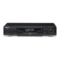
PM3392A
CH1:2.00 V= MTB 500us
TRAYIN
GND
Check MACE 7270
OK
NOK
Check
Tray In
signal at testpoint S20
during tray command
Tray Out
(testpoint S19) stays at 3V2
Execute "tray close" test
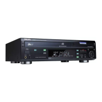
Check
TR+
(testpoint S21),
TR-
(testpoint S22) :
- values without commands 4V2
- values during "tray open" command (osc. a)
- values during "tray close" command (osc. b)
PM3392A
CH1:5.00 V=
CH2:5.00 V= MTB 500us
GNDTR-
GNDTR+
TR+
TR-
NOK
OK
PM3392A
CH1:5.00 V=
CH2:5.00 V= MTB 500us
GNDTR-
GNDTR+
osc. a
osc. b
Check CDL4009
NOK
TR+
TR-
CL06532018_020.eps
290200