CM-150 CA Product Guide14
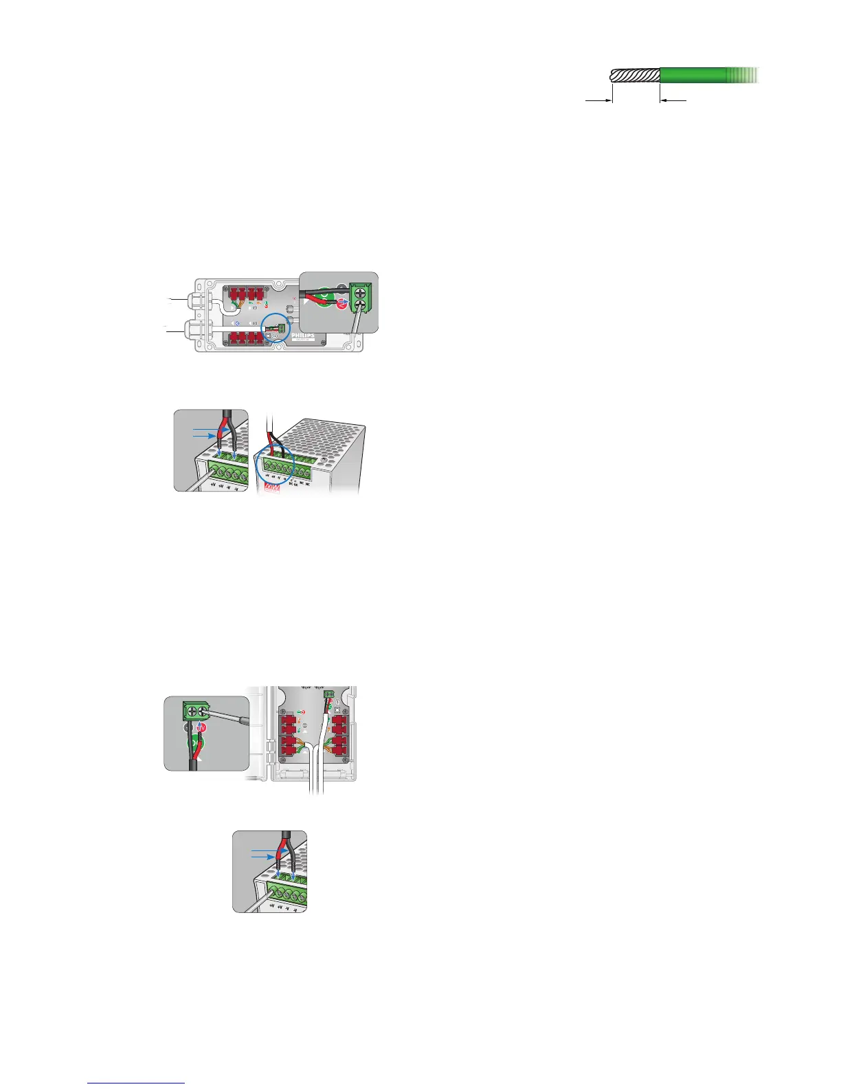
Make DC Power Connections
Surface Mount Installation
1. Run the power cable through the larger cable gland of the CM-150 CA housing.
Pull at least 127 mm (5 in) of wire into the housing.
2. Strip 5 mm (0.2 in) of insulation from the wires. If using stranded wire, twist each
wire tight to secure the wire threads.
3. Locate the DC power 2-wire terminal block connector inside the CM-150
CA housing.
4. Insert the appropriate wire (V+ and ground) in each terminal. Tighten the
retaining screws by hand with a screwdriver.
5. Tighten the cable gland around the power cable.
6. Connect the power cable to the power supply.
+V
-V
DIN Rail Mount Installation
1. Strip 5 mm (0.2 in) of insulation from the wires. If using stranded wire, twist each
wire tight to secure the wire threads.
2. Run the DC power cable through the bottom of the CM-150 CA housing. Pull at
least 127 mm (5 in) of wire into the housing.
3. Locate the DC power 2-wire terminal block connector inside the CM-150
CA housing.
4. Insert the appropriate wire (V+ and ground) in each terminal. Tighten the
retaining screws by hand with a screwdriver.
6. Connect the power cable to the power supply.
+V
-V
E The terminal block connectors
accept wire sizes from 0.5 to 2.1 mm
2
(14 to 20 AWG).
B Power supply must be isolated type.
For 7.5 V Flex, power supply must not
exceed 7.7 VDC. For 12 V Flex, power
supply must not exceed 12.3 VDC.
For 24 V Flex, power supply must not
exceed 24.5 VDC.