Overcurrent Protection Circuit
This circuit consists of R3145, C2143, a thyristor
circuit formed by T7141 and T7143, R3143 and
R3142. When the output is shortened, the cur-
rent through the FET will produce a large voltage
drop across the source resistors of the FET. That
voltage turns On 7140 and 7143. The thyristor
circuit will start to conduct and switch Off the
supply voltage to C2140. This switches Off the
drain current of the MOSFET, 7125. The start cir-
cuit will try to start up the power supply again. If
the short still exists, the complete start and stop
sequence will repeat. The power supply is in a
hiccup mode and is ticking.
Overvoltage Protection Circuit
This circuit consists of R3149, D6144, 6143,
R3144, C2142 and T7142. If the regulation cir-
cuit does not function due to an error in the con-
trol loop, the regulated output voltage will
increase. This overvoltage is sensed on the hot
ground side of the transformer at Pins 7 and 8.
When an overvoltage is detected, the circuit will
activate the thyristor circuit T7141 and 7142. The
power supply will be shutdown as long as the
error in the control loop is present.
Secondary Rectifier/Smoothing Circuit
There are six Rectifier/Smoothing circuits on the
secondary side. Each supply voltage depends on
the number of windings in the transformer. From
these circuits, several voltages are derived and
fed to three connectors. The following voltages
are present at the output: 33Vdc, 12Vdc, 3.9Vdc,
and 5Vdc Stby, -5Vdc Stby, and -33Vdc Vgnstby.
The +12V is switched Off by the STBY_Ctrl sig-
nal, ION. The -33Vdc is dedicated to the Front
Panel Fluorescent Tube as a grid supply. The
FLYB signal is used as a Power Fail and mea-
surement signal.
Front Panel
The main elements of the Front Panel are the
microcomputer, 7156, the Display Tube, and the
keyboard. Refer to Figure 18. 7156 is an 8 bit
microcomputer fitted with 96kB ROM and 3kB
RAM and is responsible for the following func-
tions:
Fluorescent Display driver
Monitoring the keyboard matrix
Decoding the remote control commands
from the infrared receiver, 6170.
Activation of the display
The Fluorescent Tube operates using a grid and
segment scanning matrix. AC is supplied by a
switching regulator consisting of 7151, 7152,
7153, and 5153. With AC supplied, the micro-
computer scans the elements in the tube to
determine what segments light up. The system
clock is generated with the 12MHz crystal, 1153.
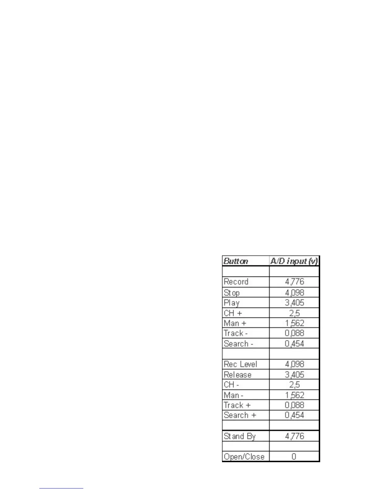
Keyboard Matrix
There are 11 different keys on the display board.
A resistor network is used to generate a specific
voltage value, depending on the key pressed, via
the resistors 3186-90, 3145, 3197, 3177-3178,
3197, and 3180. This RTL data (voltage Level) is
sent to 7156 on Pins 17, 18, 19, and 20.
Pressing keys simultaneously may lead to unde-
sired functions!
Figure 17 - RTL Voltage Chart
41