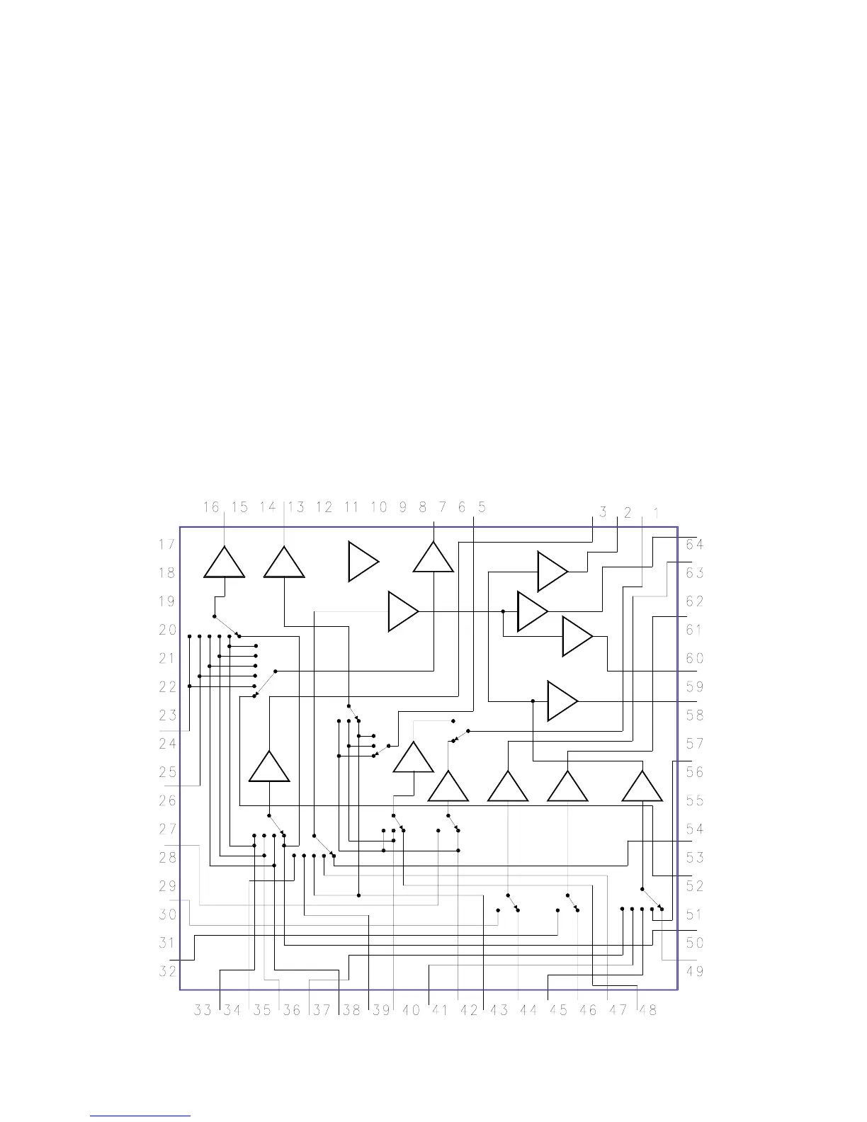
Video and Audio Routing
The A/V I/O switching is controlled by a switch-
ing matrix, 7507. Refer to Figure 47. It is con-
trolled via the I
2
C Bus. 7507 has three Y, C,
CVBS inputs. All switches have 6 dB amplifica-
tion on the outputs.
There are two CVBS input connections possible:
Front Cinch (RCA) and Rear Cinch (RCA). Both
CVBS sources are connected directly to 7507
and routed to Rear Out 1 and Rear Out 2.
Figure 48 is a internal diagram for 7507.
The Audio I/O switching is also controlled by
7507 via the I
2
C Bus. Analog Audio coming from
Rear External Inputs 1,2, and External 3 are
capacitively coupled to IC7507, Pins 35, 37, 53,
and 56. Digital Board input and Tuner Audio is
routed via 7600 to 7507, Pins 39 and 41. 7507
selects the audio source.
Figure 48 - IC7507 Internal Circuit
84