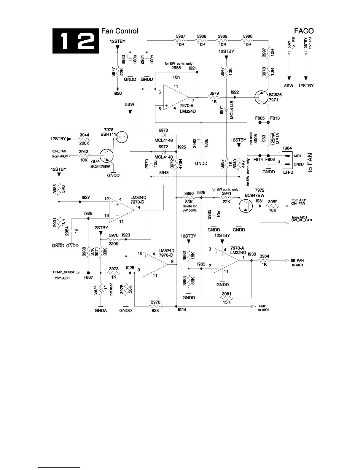
Fan Control
The Fan Control circuit is necessary to control
the speed of the cabinet fan, 1984, and the BE
Fan according to the changes of temperature
and motor noise. The temperature is measured
via a Negative Temperature Coefficient, NTC,
thermistor on the IR Receiver Board, 3135. The
sensor’s output voltage is labeled Temp_Sense.
The Fan Control circuit uses Op Amps to gain
control of the sensor’s signal. When the temper-
ature is lower than 25°C the cabinet fan’s volt-
age is approximately. 5V and will reach approxi-
mately 10V at a temperature of 40°C. The
Microcomputer controls the On/Off function of
the two fans via control line ION_FAN and
SW_BE_FAN. The TEMP signal goes to the
Microcomputer and the inputs of the Op Amps.
The Microcomputer supplies the Motor On
switching voltages. The speed of both fans are
controlled by the Temp_Sense line going into the
Op Amps.
90
Figure 54 - Fan Control Circuit