Do you have a question about the Philips DVP5150/94 and is the answer not in the manual?
| Video Playback System | NTSC, PAL |
|---|---|
| Progressive Scan | Yes |
| Remote Control | Yes |
| Power Consumption | 15 W |
| Video Formats | MPEG-1, MPEG-2 |
| Audio Formats | MP3, WMA, Dolby Digital, DTS |
| Output Connections | Composite video, Component video, Digital Coaxial Audio, Analog Audio |
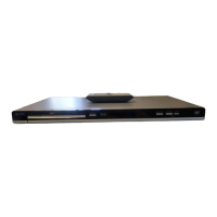
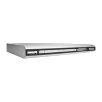
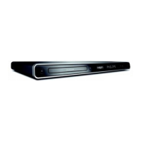
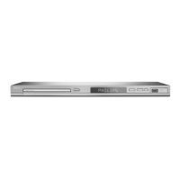
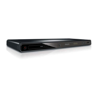
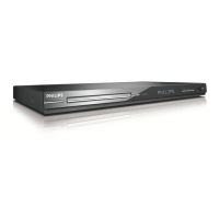
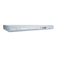
| Dimensions | 360 x 230 x 45 mm |
| Video D/A Converter | 10 bit / 27 MHz |
| Audio D/A Converter | 24 bit / 192 kHz |
| Playback Media | DVD, CD, CD-R, CD-RW, DVD+R, DVD+RW, DVD-R, DVD-RW |
| Video Playback Formats | MPEG-2, MPEG-1 |
| Surround Sound | Dolby Digital |
| Disc Compatibility | DVD, CD, VCD |
| Output Resolution | Up to 1080i |
Wiring connections for the DVD loader assembly (ASA WXD8829 + KHM313A).
Wiring connections for the switch board (CN303).
Wiring connections for the main board, including MTK1389C.
Wiring connections for the VFD/Key/PT6312 front board (CN301, CN302).
Wiring connections for the power supply unit (CN202).
Component layout and connections on the front board's top surface.
Component layout and connections on the front board's bottom surface.
Physical layout of components on the switch board's bottom.
Component placement and routing on the power board's underside.
Schematic detailing MPEG and Servo sections of the main board.
Schematic for SDRAM, Flash, EEPROM, and Video Output circuitry.
Schematic illustrating the Audio DAC and Audio Output stages.
Component placement on the top side of the main board.
Component placement on the bottom side of the main board.
Diagram showing the physical assembly of the DVD player components.
List of spare parts for main casings and accessories.