DISASSEMBLY ADVISE IRON
PCS 101 314
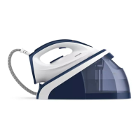
BACK PLATE 12
remove SCREW A
INLAY 1
remove LAMP 10
remove MICRO SWITCH 2
ADJUSTMENT AND CONTROLS
Thermostat 13
Thermostat ( 13 ) supplied as a spare part or fi tted to
the sole plate ( 9 ) has already been a djusted by the
supplier and secured by glue.
To avoid disfunction of the iron , NEVER readjust the
thermostat.
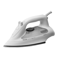
HANDLE 6
remove THERM. DIAL 4
remove SCREW B (4x)
unlock HANDLE carefully
SKIRT 8
remove ELECTRICAL
WIRES
remove EXTENSION
PIECE 5
remove SPRING CLAMP
FROM STEAM HOSE
remove SCREW C (3x)
Bend back the contact points
THERMOSTAT 13
ONLY
cut CONDUCTOR A
at location P
remove SCREW D
P
Q
B
A
D
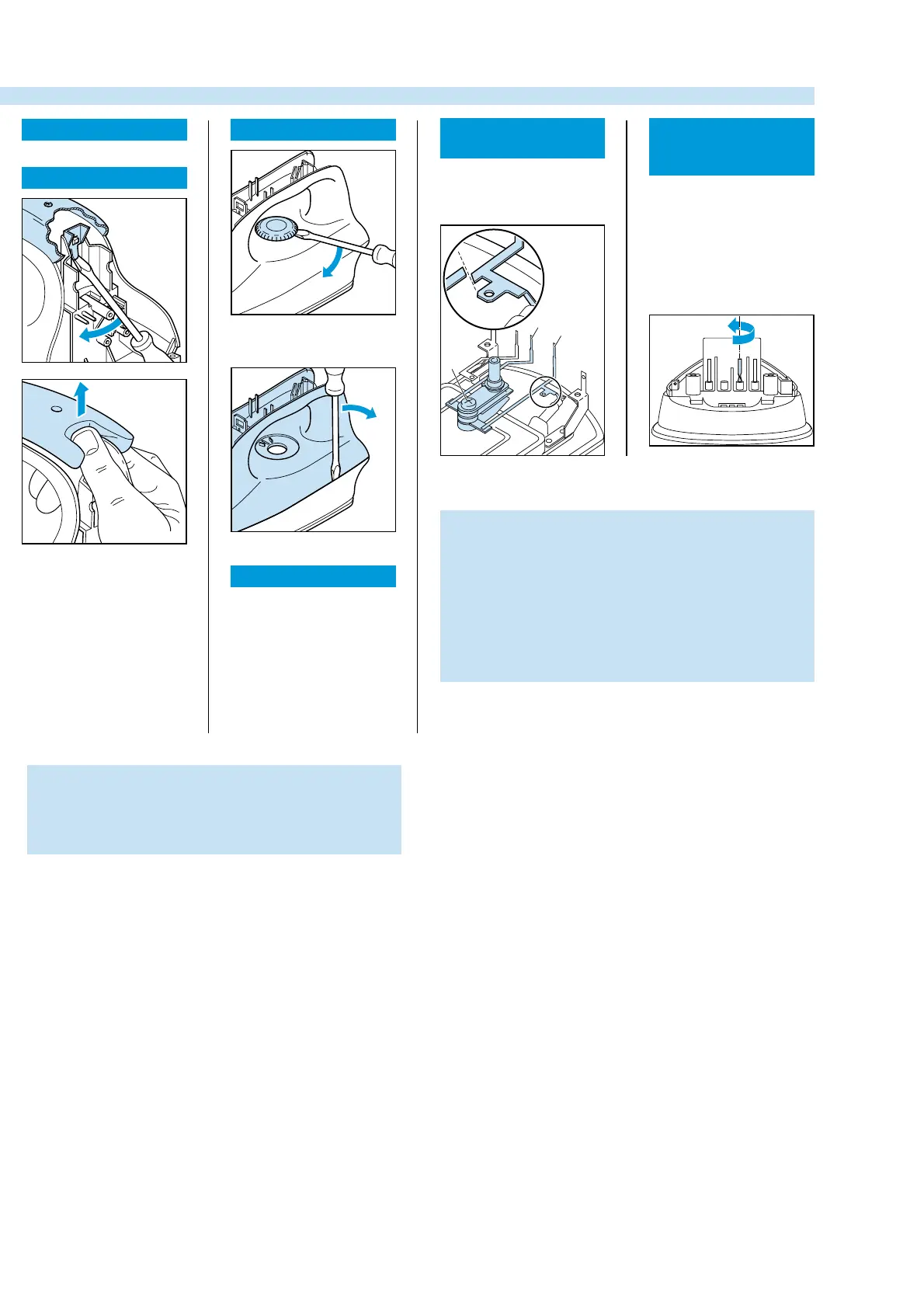
ASSEMBLY
REQUIREMENTS
THERMOSTAT 2
Instead of metal conductor A,
the new thermostat has a wire
with AMP clamp.
After fi xing screw D, connect
the AMP clamp to tag Q.
After assembling SKIRT 8
ALWAYS turn conductor B
through 180 degrees.
NOTE :
For opening you need a Torx screwdriver 362 TR
T20 x 100.