3 - 1 3 - 1
DISASSEMBLY INSTRUCTIONS
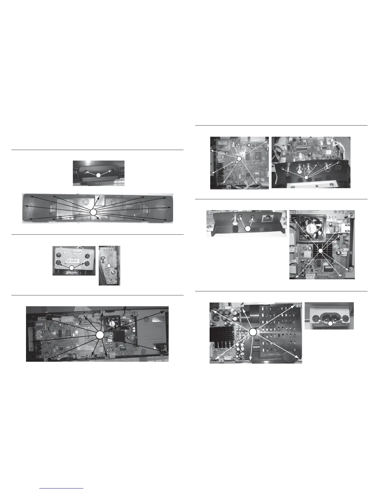
Dismantling of the Rear Panel Assemble
1) Loosen 2 screws “A” at the rear panel to remove rear stand as shown in gure 1.
2) Loosen 12 screws “B” at the rear panel to remove rear panel as shown in gure 2.
Figure 8
Figure 1
Figure 2
Figure 3
Figure 4
Dismantling of the Main Board
1) Loosen 6 screws “F” on the top of main board as shown in gure 6.
2) Loosen 5 screws “G” at the main board jack bracket to remove the main board as shown in gure 7.
Figure 6
Dismantling of the BD Board
1) Loosen 2 screws “H” at the BD board jack bracket as shown in gure 8.
2) Loosen 6 screws “I” to remove BD board as shown if gure 9.
Figure 10
Note:In some service positions the components or copper patterns of one board may risk touching its
neighbouring pc boards or metallic parts. To prevent such short-circuit use a piece of hard paper or
other insulating material between them.
A
B
Dismantling of the WIFI & MP3 Board
1) Loosen 2 screws “C” on the top of WIFI board as shown in gure 3.
2) Loosen 2 screws “D” on the top of MP3 board as shown in gure 4.
C
Dismantling of the PCB Bractket
1) Loosen 9 screws “E” at the PCB bracket as shown in gure 5.
D
F
G
Figure 7
H
I
Figure 9
Dismantling of the Power Board
1) Loosen 6 screws “J” to remove the power board as shown in gure 10.
2) Loosen 2 screws “K” to remove the AC socket as shown in gure 11.
J
K
Figure 11
E
Figure 5
 Loading...