3 - 2 3 - 2
SERVICE POSITIONS
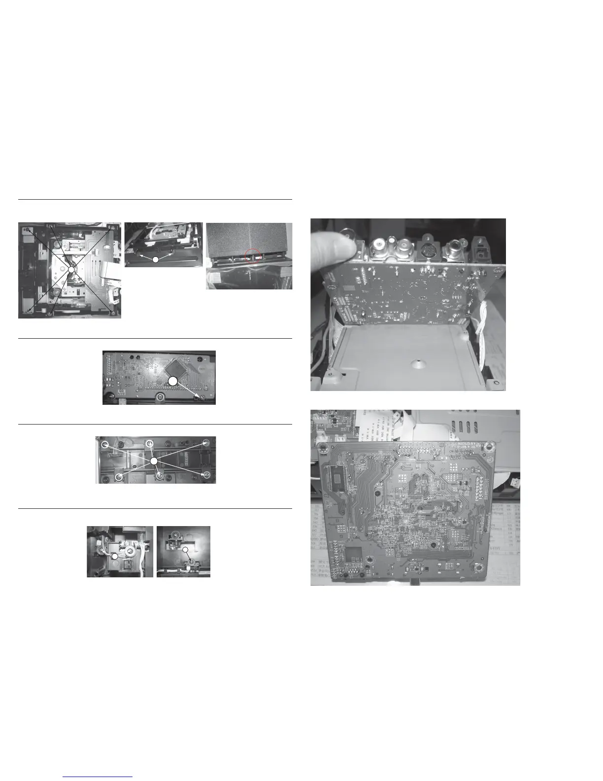
Dismantling of the BD Module
1) Loosen 6 screws “L” as shown in gure 12.
2) Loosen 2 screws “M” to remove the BD module as shown in gure 13.
Note: When install the BD module, please note the part of as shown in gure 14.
Figure 12
Figure 13
Service Position A - Main Board
Service Position B - BD Board
L
M
Dismantling of the VFD Board
1) Loosen 1 screw “N” on the top of VFD board to remove the VFD board as shown in gure 15.
N
O
Figure 15
Figure 16
Dismantling of the Touch Board
1) Loosen 6 screws “O” to remove the Touch board as shown in gure 16.
Dismantling of the Stop SW+Open SW+Close SW Board & Damper
1) Loosen 2 screws “P” to remove stop sw+open sw board as shown in gure 17.
2) Loosen 1 screws “Q” to remove close sw board as shown in gure 18.
Figure 14
P
Q
Figure 17 Figure 18
 Loading...