EasyManua.ls Logo

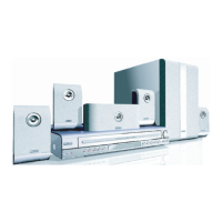
Philips HTS5500/37/55 User Manual

Philips HTS5500/37/55
56 pages
To Next Page IconTo Next Page
Page #1 background imageLoading...
Page #1 background image
Published by KC-TE 0519 AV Systems Printed in the Netherlands Subject to modi cation EN 3139 785 31200
HTS5500C/37/55
DVD Player
CLASS 1
LASER PRODUCT
1 Technical Speci cations and Connection
Facilities 2
Location of PC Boards 2
Technical Speci cations 3
Measurement Setup 4
Service Aids 5
Lead Free Requirements 7
2 Dismantling instructions & Service Positions 8
Dismantling instructions 8
3 Diagnostic Software 10
Service test program 10
4 Set Block diagram 13
5 Set wiring diagram 14
6 Panel Front Boards 15
Front Display - Component Layout 15
Front Display - Chip Layout 15
Front Display - Circuit Diagram 16
Key & Open/close Board - Component Layout 17
Key & Open/close Board - Chip Layout 17
Key & Open/close Board - Circuit Diagram 18
Front key board - Component Layout 19
Front key board - Chip Layout 19
Front key board - Circuit Diagram 20
Video Connector Board - Circuit Diagram 21
Video Connector Board - Component Layout 22
Video Connector Board - Chip Layout 22
7 AV Board 23
AV Board - Top view layout 23
©
Copyright 2005 Philips Consumer Electronics B.V. Eindhoven, The Netherlands.
All rights reserved. No part of this publication may be reproduced, stored in
a retrieval system or transmitted, in any form or by any means, electronic,
mechanical, photocopying, or otherwise without the prior permission of Philips.
Version 1.0
Contents PageContents Page
AV Board - Bottom view layout 24
AV Board - Circuit Diagram (Part 1) 25
AV Board - Circuit Diagram (Part 2) 26
AV Board - Circuit Diagram (Part 3) 27
AV Board - Circuit Diagram (Part 4) 28
AV Board - Circuit Diagram (Part 5) 29
AV Board - Circuit Diagram (Part 6) 30
8 Powerbox Spk Assy SW5500C 31
Power Supply Unit - Top view layout 31
Power Supply Unit - Circuit Diagram (Part 1) 32
Power Supply Unit - Circuit Diagram (Part 2) 33
Interface - Top view layout 34
Interface - Circuit Diagram (Part 1) 35
Main Amplifer - Top view layout 36
Main Amplifer - Bottom view layout 37
Connector schematic 38
FR+SURROUND ampli er schematic 39
Subwoofer Amplifer - Top view layout 40
Subwoofer Amplifer - Bottom view layout 41
Subwoofer ampli er schematic 42
Transformer - Top silk layout 43
Exploded View - Box Spk Assy SW5500C 44
Exploded View - Module 45
Wiring Diagram SW5500C 46
9 Module SD6.3 CH HT 47
SD6.3 CH HT Board - Top View Layout 47
SD6.3 CH HT Board - Bottom View Layout 48
SD6.3 CH HT Board - Circuit Diagram (Part1) 49
SD6.3 CH HT Board - Circuit Diagram (Part2) 50
10 Set Mechanical Exploded View 51
11 Partlist 53

Table of Contents

Question and Answer IconNeed help?

Do you have a question about the Philips HTS5500/37/55 and is the answer not in the manual?

Philips HTS5500/37/55 Specifications

General IconGeneral
DVD player includedYes
HDMI ports quantity1
USB portYes
Audio output channels5.1
Supported disc typesCD, DVD
Video formats supportedMPEG2
Image formats supportedJPEG
ConnectivityUSB

Summary

Technical Specifications and Connection Facilities

Location of PC Boards

Diagram showing the physical placement of internal circuit boards within the unit.

Technical Specifications

Detailed electrical and performance parameters of the device.

Measurement Setup

Procedures and equipment for testing device performance parameters.

Service Aids

Tools and accessories recommended for service and repair.

Lead Free Requirements

Guidelines for handling and soldering lead-free components.

Dismantling Instructions & Service Positions

Dismantling Procedures

Step-by-step guides for disassembling the changer and modules.

Service Positions

Recommended orientations and configurations for servicing the unit.

Diagnostic Software

Service Test Program

Steps to activate and use the built-in diagnostic test program for troubleshooting.

System Diagrams

Set Block Diagram

High-level overview of the device's internal functional blocks and connections.

Set Wiring Diagram

Detailed schematic illustrating electrical connections between all components.

Panel Front Boards

Front Display Components

Component layout, chip layout, and circuit diagram for the front display.

Key & Open/Close Board Components

Component layout, chip layout, and circuit diagram for the key board.

Front Key Board Components

Component layout, chip layout, and circuit diagram for the front key board.

Video Connector Board Components

Component layout, chip layout, and circuit diagram for the video connector board.

Safety and Precautions

ESD Protection

Guidelines for handling components sensitive to electrostatic discharge.

Safety Regulations

Warnings and regulations regarding repair, parts, and laser safety.

AV Board

AV Board Layouts

Top and bottom view component layouts for the AV board.

AV Board Circuit Diagrams

Detailed circuit diagrams (Parts 1-6) for the AV board.

Powerbox Spk Assy SW5500C

Power Supply Unit

Top view layout and circuit diagrams (Parts 1-2) for the power supply unit.

Interface Components

Top view layout and circuit diagram (Part 1) for the interface board.

Main Amplifier Components

Top and bottom view component layouts for the main amplifier.

Connector Schematic

Diagram illustrating pin assignments for various connectors.

FR+SURROUND Amplifier Schematic

Circuit diagram for the front and surround amplifier section.

Subwoofer Amplifier Components

Top view, bottom view, and schematic for the subwoofer amplifier.

Transformer Layout

Top silk layout of the transformer.

Exploded Views

Visual breakdown of the subwoofer assembly and its modules.

Wiring Diagram SW5500C

Overall wiring diagram connecting major assemblies.

Module SD6.3 CH HT

SD6.3 CH HT Board Layouts

Top and bottom view component layouts for the SD6.3 CH HT board.

SD6.3 CH HT Board Circuit Diagrams

Circuit diagrams (Part 1-2) for the SD6.3 CH HT board.

Set Mechanical Exploded View

Spare Parts List

Miscellaneous and Accessories Parts

List of mechanical, accessory, and general electronic parts.

Subwoofer Parts

Spare parts specific to the active subwoofer assembly.

Electrical Parts Lists

Lists of electronic components by board type (Front Panel, AV, etc.).

Diodes

Part numbers and descriptions for diodes used in the device.

Transistors & Integrated Circuits

Part numbers for transistors and ICs.

Resistors

Part numbers for resistors.

Related product manuals