Mechanical Instructions
EN 12 LC7.2E LA4.
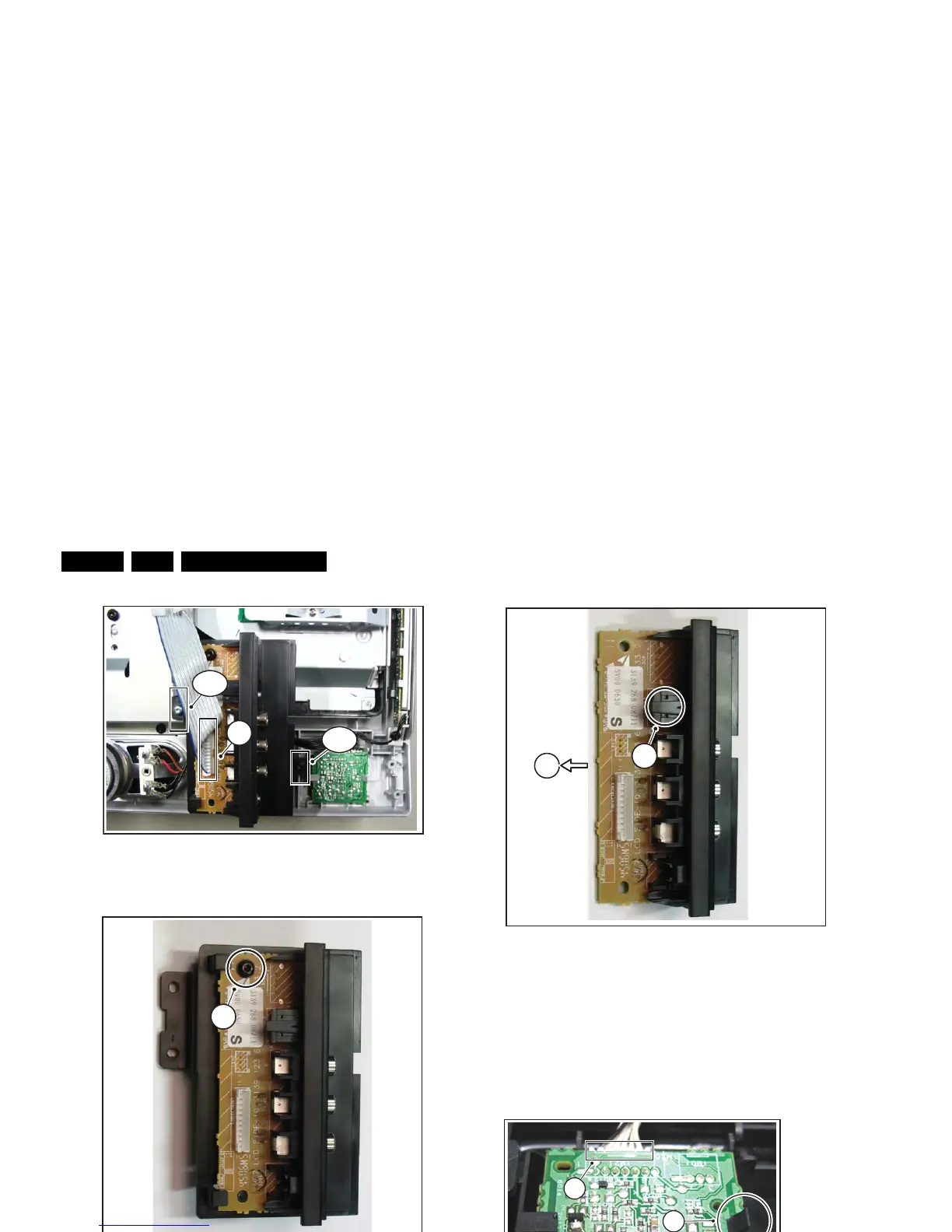
Figure 4-9 Side I/O module
Figure 4-10 Side I/O panel [1/3] top side
Figure 4-11 Side I/O panel [2/3] bottom side
Figure 4-12 Side I/O panel [3/3]
4.3.4 IR/LED Panel
1. Refer to next figure (is taken from the 32” model, but the
method is comparable for the other screen sizes).
2. Unplug connector(s) [1].
3. Release clip [2] and remove the board.
When defective, replace the whole unit.
Figure 4-13 IR/LED panel
G_16860_066.ep