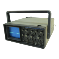
The Philips PM3207 is a 15 MHz dual-channel oscilloscope designed for educational, research, and service applications. It is a compact and lightweight instrument, featuring ergonomic design and extensive measurement capabilities.
Function Description
The PM3207 functions as an oscilloscope, allowing for the visualization and measurement of electrical signals over time. It features two input channels (A and B) for simultaneous display of two signals, or for displaying a single signal with various triggering and display modes. The instrument includes controls for vertical deflection (amplitude), horizontal deflection (time base), and triggering, enabling users to capture and analyze waveforms effectively.
Important Technical Specifications
CRT (Cathode Ray Tube):
- Measuring area: 8 x 10 divisions (1 division = 1 cm)
- Screen type: P31 (GH), with optional P7 (GM)
- Total acceleration voltage: 1.5 kV
Vertical Amplifier:
- Display modes: A; A±B; ±B; A and B (chopped in ms – alternated in µs position)
- Input coupling: AC/DC
- Bandwidth: DC: 0 Hz...15 MHz (-3 dB); AC: 10 Hz...15 MHz (-3 dB)
- Deflection accuracy: ±5%
- Input impedance: 1 MΩ // 35 pF
- Max. permissible input voltage: 400 V (DC + AC peak)
- Chopper frequency: 100 kHz approx.
Time Base:
- Coefficient error: ±5%
- Additional error for x5 magnifier: ±2%
Trigger:
- Source: Channel A, Channel B, or External (EXT)
- Mode: AC/TV
- Sensitivity:
- INT: 0.75 DIV (Trigger freq. ≤ 1.5 DIV) | Trigger freq. > 1.5 DIV
- EXT: 0.75 V (≤ 100 kHz) | 1.5 V (> 100 kHz)
- Trigger frequency range: 10 Hz...15 MHz
- Input impedance: 1 MΩ // 35 pF
- Max. permissible input voltage: 400 V (DC + AC peak)
X-deflection:
- Source: Y A input; Time base
- Frequency range: DC: 0...2 MHz (-3 dB)
- Phase shift: 3° at 10 kHz
Power Supply:
- Nominal voltage range: 110; 220; 240 VAC ± 10%
- Nominal frequency range: 48...66 Hz
- Power consumption: 25 W (32 VA) max.
Mechanical Data:
- Length: 370 mm incl. controls (450 mm incl. handle)
- Width: 297 mm excl. handle (330 mm incl. handle)
- Height: 129 mm excl. feet (138 mm incl. feet)
- Weight: 4.6 N (4.7 kg)
Optional Accessories:
The manual lists several optional accessories, primarily passive probes of various lengths and attenuation ratios (1:1/10:1, 1:1), as well as a current probe, and a compatible viewing hood.
Usage Features
The PM3207 is designed for ease of use, with clearly labeled controls.
- Local Mains (Line) Connection: Before connecting the instrument to the mains, users must ensure that the set voltage matches the local mains voltage. The instrument can be set to 110 V, 220 V, or 240 V. If the instrument needs to be set to another voltage, local service organization should be contacted.
- Controls and Sockets:
- Cathode-ray tube and power controls:
- POWER (1): Mains switch; pilot lamp indicates ON-state.
- INTENS (2): Trace-brilliance control; clockwise turning increases brilliance of the trace (spot).
- FOCUS (3): Beam-focussing control; enables focusing of beam for minimum spot size. For correct display, FOCUS and INTENS should be optimally adjusted.
- Vertical deflection:
- POSITION (4): Control (by turning) for vertical shifting of the trace (spot).
- AMPL/DIV (5): Control of vertical deflection coefficients, ranging from 5 mV/DIV up to 10 V/DIV in a 1-2-5 sequence. In the "OFF" position, the input is floating and no trace will be displayed. If both "AMPL/DIV" switches are in "OFF"-position, the base line of channel B is displayed only.
- AC (6): Input signal coupled via a blocking capacitor and the DC component is blocked. Input signal directly coupled.
- A&B (7): Both channels are displayed, chopped (ms) or alternated (µs).
- ADD (8): Sum signal of channels A and B will be displayed (set "A+/-").
- + (9): Slide switch: In "+" position for usual operation. In "-" position the inverted signal of the channel B will be displayed. In combination with ADD, A-B will be displayed.
- A (10): BNC-socket for channel A input.
- B (11): BNC-socket for channel B input.
- Time-base and horizontal deflection:
- X POSITION (12): Control (by turning) for horizontal shifting of the trace (spot).
- LEVEL (13): Control for adjusting the point (level) on the input signal slope from which the trigger signal is derived.
- µs/ms (14): Slide switch; in combination with the TIME/DIV switch, selects the time coefficients. In A&B mode the display is chopped in position ms and alternated in position µs.
- MAGN x1/x5 (15): Slide switch; allows increase of the horizontal deflection by a factor of 5.
- TIME/DIV (16): In combination with the µs/ms switch, selects the time coefficients from 0.5 µs/DIV to 200 ms/DIV in a 1-2-5 sequence.
- X VIA A (17): In the position X via A, horizontal deflection is determined by the channel A input signal (bandwidth <= 2 MHz).
- A/B (18): Slide switch; triggering is effected on the signal derived from channel A or B, depending on the switch position.
- + (19): Slide switch; enables triggering on the positive-going (+) or negative-going (-) slope of the input signal.
- INT/EXT (20): Slide switch; the time base can trigger either on a signal derived from channel A or B, or on a signal applied to BNC connector EXT.
- AC/TV (21): Slide switch; normal triggering. DC component of the trigger signal is blocked. TV line or TV frame synchronisation is obtained. (Frame in position ms, and line in position µs).
- EXT (22): BNC socket for external trigger input.
Maintenance Features
- Important Note: The design of this instrument is subject to continuous development and improvement. Consequently, this instrument may incorporate minor changes in detail from the information contained in the manual.
- Safety Regulations (in accordance with IEC 348):
- Before connecting the instrument to the mains, visually check the cabinet, controls, and connections, etc., to ascertain that no damage has occurred in transit. If any defects are apparent, do not connect the instrument to the mains.
- The instrument must be disconnected from all voltage sources, and any high voltage points discharged before any maintenance or repair work is carried out.
- If adjustment or maintenance of the operating instrument with covers removed is inevitable, it must be carried out only by skilled personnel who are aware of the hazards involved.
- In normal operation, the double-insulated power supply obviates the need for a safety ground.
- Warning: It is of utmost importance to always bear in mind that in all measurements, the frame ground of the oscilloscope is raised to the same potential as that of the measuring ground probe connection. Neither the probe's ground lead nor the frame ground shall be connected to live potentials.
- Rechange des pièces détachées (Réparations): In case of correspondence and claims regarding this device, always indicate the type number and serial number marked on the characteristic plate. This ensures that the correct parts and information are provided for maintenance.