105
3.2.
CIRCUIT
DESCRIPTION
3.2.1
.
Vertical
deflection
system
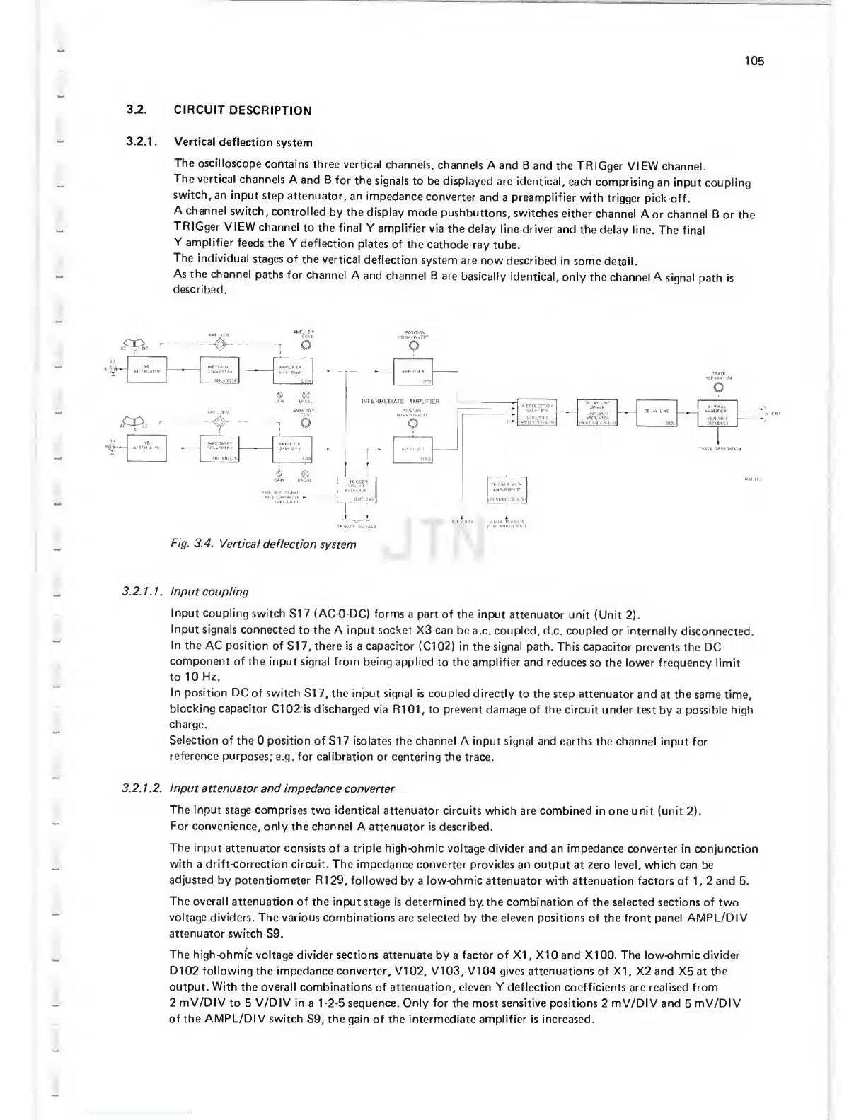
The
oscilloscope
contains
three vertical
channels,
channels A
and B and
the TRIGger
VIEW
channel.
The
vertical
channels
A and B
for
the signals
to be displayed
are identical,
each
comprising
an input coupling
switch,
an input
step attenuator,
an impedance
converter
and
a
preamplifier
with
trigger
pick-off.
A
channel
switch,
controlled
by the display
mode
pushbuttons,
switches either
channel
A
or
channel
B
or the
TRIGger
VIEW channel
to the
final Y
amplifier
via the
delay line
driver
and the
delay line.
The
final
Y
amplifier
feeds
the
Y
deflection
plates
of the
cathode-ray
tube.
The
individual
stages
of the
vertical
deflection
system
are now
described
in some
detail.
As
the channel
paths for
channel
A and
channel B
are
basically
identical, only
the channel
.A
signal
path
is
described.
Fig. 3.4.
Vertical
deflection
system
3.
2.1.1. Inpu
t coupling
Input coupling
switch SI
7
(AC-O-DC) forms
a part of the input
attenuator unit
(Unit
2).
Input
signals
connected
to
the A input
socket X3 can
be a.c. coupled,
d.c. coupled
or internally
disconnected.
In the
AC position
of SI
7,
there
is a capacitor
(Cl
02)
in
the signal path. This
capacitor
prevents the
DC
component
of
the input signal from being
applied
to
the
amplifier
and reduces
so
the lower
frequency limit
to 10
Hz.
In position DC
of switch
SI
7,
the input signal is coupled
directly
to
the
step attenuator
and
at
the same
time,
blocking
capacitor
Cl
02 is
discharged via R101,
to
prevent
damage of the circuit
under test
by a
possible high
charge.
Selection of
the
0
position of
SI 7 isolates the channel
A input signal and earths
the
channel
input
for
reference
purposes;
e.g. for calibration
or centering the
trace.
3.2.
1 .2.
Input
attenuator and impedance
converter
The input
stage comprises
two
identical
attenuator
circuits which
are combined in
one unit (unit
2).
For convenience,
only the channel
A attenuator is described.
The input
attenuator consists
of a triple high-ohmic voltage divider and
an
impedance
converter in conjunction
with
a
drift-correction circuit.
The impedance converter provides
an output
at
zero level,
which can be
adjusted by
potentiometer
R129,
followed
by a
low-ohmic
attenuator with
attenuation factors of
1,
2 and 5.
The overall attenuation
of the input
stage is
determined
by. the combination of the selected
sections of two
voltage dividers.
The various combinations
are
selected
by the
eleven
positions of the front panel AMPL/DIV
attenuator
switch
S9.
The high-ohmic
voltage divider sections attenuate by
a
factor
of
XI
,
XI
0
and
XI
00.
The low-ohmic divider
D102 following
the impedance converter, VI
02,
V103, V104 gives
attenuations of XI, X2 and X5
at
the
output. With
the overall combinations
of attenuation, eleven
Y
deflection coefficients
are realised
from
2
mV/DIV
to 5
V/DIV
in
a
1-2-5
sequence. Only for the
most sensitive positions 2 mV/DIV and 5 mV/DIV
of the AMPL/DIV switch
S9,
the gain of the intermediate amplifier is increased.
 Loading...

