11
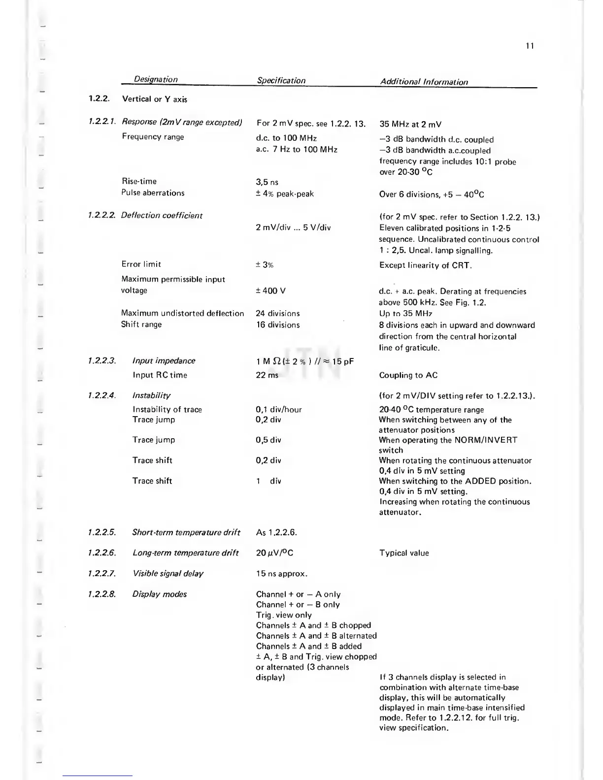
Designation
Specification
Additional
Information
1.2.2.
Vertical
or Y
axis
1.2.2.
1.
Response
(2m
V
range
excepted)
For
2 mV
spec, see
1.2.2. 13.
35 MHz
at 2 mV
Frequency
range
d.c. to 100
MHz —3
dB
bandwidth
d.c.
coupled
a.c.
7 Hz
to
100
MHz
—3
dB
bandwidth
a.c.coupled
frequency
range includes
10:1 probe
over
20-30
°C
Rise-time
3,5
ns
Pulse
aberrations
±
4%
peak-peak
Over 6
divisions,
-t5
—
40°C
1.22.2.
Deflection
coefficient
2
mV/div
...
5
V/div
(for 2 mV
spec, refer
to Section 1.2.2.
13.)
Eleven calibrated
positions in
1-2-5
sequence.
Uncalibrated continuous
control
1 :
2,5.
Uncal. lamp
signalling.
Error
limit
±3%
Except linearity
of CRT.
Maximum
permissible input
voltage
±400 V
d.c.
+
a.c.
peak. Derating
at
frequencies
above 500 kHz.
See
Fig. 1.2.
Maximum
undistorted
deflection 24 divisions Up to 35 MHz
Shift
range
16
divisions
8 divisions each in upward and downward
direction from
the central horizontal
line
of
graticule.
1.2.
2.3.
Input
impedance
1
M12(±2%
)
//^ 15pF
Input RCtime
22 ms Coupling to AC
I.2.2.4. Instability
(for 2 mV/DIV
setting
refer
to 1.2.2.13.).
Instability of
trace
0,1
div/hour
20-40
°C
temperature range
Trace jump
0,2
div When switching
between any of the
attenuator positions
Trace jump
0,5
div When
operating the
NORM/INVERT
switch
Trace shift
0,2
div When
rotating the continuous attenuator
0,4
div in 5
mV setting
Trace shift
1
div When
switching
to the
ADDED
position.
0,4
div in
5 mV setting.
Increasing when rotating the continuous
attenuator.
1.22.5. Short-term
temperature drift As 1.2.2.6.
1.2.
2.6.
Long-term
temperature drift
20
mV/°C
Typical value
1.2.2.
7.
Visible signal delay
15 ns approx.
1. 2.2.8. Display modes Channel
+
or
—
A only
Channel
+
or
—
B only
Trig, view only
Channels
±
A and
±
B chopped
Channels
±
A and
±
B
alternated
Channels
±
A
and
±
B added
±
A,
±
B and Trig, view
chopped
or
alternated
(3
channels
display)
If
3
channels display is selected
in
combination with alternate time-base
display,
this
will
be
automatically
displayed in main time-base intensified
mode. Refer
to
1 .2.2.1
2.
for full trig,
view specification.