157
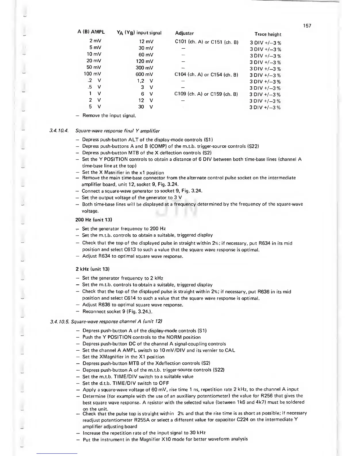
A
(B)
AMPL
Ya
(Yb)
input
signal
Adjuster
Trace
height
2 mV
12 mV C101
(ch. A)
or Cl
51 (ch. B)
3
DIV
t-/-3%
5
mV
30
mV
-
3DIV+/-3%
10 mV
60
mV
-
3DIV-t-/-3%
20 mV
120 mV
-
3DIV-h/-3%
50 mV
300
mV
-
3DIV-t/-3%
100 mV
600
mV Cl
04
(ch. A)
or Cl
54 (ch.
B)
3 DIV
-^/-3%
.2
V
1,2 V
3
DIV
+/-3%
.5 V
3 V
3
DIV +/-3%
1
V
6 V
Cl
09
(ch.
A) or
Cl
59 (ch. B)
3 DIV
-i-/-3%
2 V
12
V
-
3DIV+/-3%
5 V
30
V
3DIV-h/-3%
—
Remove the
input signal.
3.4.
10.4. Square-wave
response final Y
amplifier
—
Depress push-button
ALT of the display-mode controls (SI
)
—
Depress
push-buttons A and
B (COMP)
of the m.t.b. trigger-source controls
(S22)
—
Depress push-button MTB of the
X
deflection controls
(S2)
—
Set the
Y
POSITION controls
to
obtain a distance of 6 DIV
between both time-base
lines
(channel
A
time-base line
at
the
top)
—
Set the
X Masnifier
in the
x1
position
—
Remove the main time-base connector from the alternate
control pulse socket on the intermediate
amplifier board,
unit
12,
socket
9,
Fig. 3.24.
—
Connect
a
square-wave generator to
socket
9,
Fig. 3.24.
—
Set
the
output voltage of the
generator
to 3 V
—
Both time-base lines will be displayed at a
frequency
determined
by
the frequency of the square-wave
voltage.
200 Hz (unit
13)
—
Set
the generator frequency to 200
Hz
—
Set
the
m.t.b.
controls
to
obtain a
suitable,
triggered display
—
Check
that the
top
of
the displayed
pulse in straight within
2%;
if necessary,
put
R634
in its
mid
position and
select C613 to such
a
value that
the square wave response
is optimal.
—
Adjust R634
to optimal
square wave response.
2 kHz (unit
13)
—
Set the generator
frequency
to 2
kHz
—
Set the m.t.b.
controls to
obtain a
suitable, triggered display
—
Check that
the top
of
the displayed
pulse is straight within
2%;
if necessary,
put
R636
in its mid
position
and select C614 to such
a
value that the
square wave response
is
optimal.
—
Adjust
R636
to
optimal
square wave response.
—
Reconnect socket
9
(Fig.
3.24.).
3.4. 10.5.
Square-wave
response
channel
A
(unit 12)
—
Depress
push-button A of
the
display-mode
controls (SI)
—
Push the Y POSITION
controls to the NORM position
—
Depress
push-button DC of the channel A signal-coupling controls
—
Set
the channel
A
AMPL
switch
to
10 mV/DIV and its vernier to CAL
-
Set the XMagnifier in the XI position
—
Depress push-button
MTB
of the
Xdeflection controls (S2)
—
Depress push-button A of the
m.t.b.
trigger-source controls
(S22)
—
Set the m.t.b.
TIME/DIV switch
to a
suitable
value
—
Set the d.t.b. TIME/DIV switch to
OFF
—
Apply a
square-wave voltage of
60
mV, rise time 1 ns, repetition
rate 2
kHz,
to
the channel A input
—
Determine
(for example with the use
of an auxiliary
potentiometer)
the value for R256
that gives the
best square
wave response. A resistor
with
the
selected
value (between
1k6
and
4k7) must be
soldered
on the unit.
—
Check
that the pulse top
is straight
within 2% and that
the rise time is as
short as
possible; if
necessary
readjust
potentiometer R255A
or
select a
different value
for capacitor
C224 on the
intermediate
Y
amplifier adjusting
board
—
Increase the
repetition rate of
the input
signal
to
30
kHz
-
Put
the
instrument in the
Magnifier X10
mode for
better
waveform
analysis
 Loading...

