161
3.4.11.
Triggering
3.4.
1 1. 1.
Trigger
slope
and
level
of
the
m.
t.b.
(unit
8)
-
Depress
push-button
A of
the
display-mode
controls
(SI)
-
Depress
push-button
MTB of
the
X deflection
controls
(S2)
—
Depress
push-button
DC of the
m.t.b.
trigger-coupling
controls
-
Depress
push-button
A of the
m.t.b.
trigger
-source
controls
(S22)
—
Depress
push-button
DC of the channel
A input-coupling
controls
-
Push
the
channel
A Y
POSITION
control
to
the
NORM
position
—
Set the
channel
A AMPL
switch
to 20 mV
and its vernier
to CAL
—
Set
the
m.t.b.
TIME/DIV
switch
to lOps and
its vernier
to
CAL
—
Set the
d.t.b.
TIME/DIV
switch
to OFF
-
Apply
a sine-wave
voltage of
120 mVp.p,
frequency
30 kHz,
to the channel
A
input
—
Centre
the
display, using
the
POSITION
controls
—
Centre
the
starting point
of the sine-wave,
using the
m.t.b.
LEVEL control
—
Check
that the
starting
point of the signal
does not move
when the
SLOPE
switch is
set from
-r
to
—
;
if necessary,
readjust
potentiometer
R860
on the
trigger-amplifier
board
—
Push
the SLOPE
switch
to
its
+
position
—
Check that
the time-base
generator
starts
on
the
p>ositive-going
edge of the
sine-wave
and moves
upwards
when the
LEVEL
potentiometer is
turned clockwise
—
Pull
the
SLOPE switch
to
its
—
position
—
Check
that the time-base
generator
starts on the negative-going
edge of the
sine-wave.
—
Set
the
channel
A AMPL switch
to
5
mV/DIV
—
Rotate the
m.t.b. LEVEL
control fully clockwise
and fully anti-clockwise
—
Check
that
in
both extreme
positions the time-base
generator cuts out and
that the NOT TRIC'D lamp
lights
up
—
Increase
the amplitude of the input
signal
to
1
60
mVp.p
—
Rotate
the m.t.b.
LEVEL control fully clockwise and
anti-clockwise
—
Check
that in
both extreme positions
the trace remains triggered
and that the
NOT TRIC'D
lamp
does
not
light up
—
Remove
the input
signal.
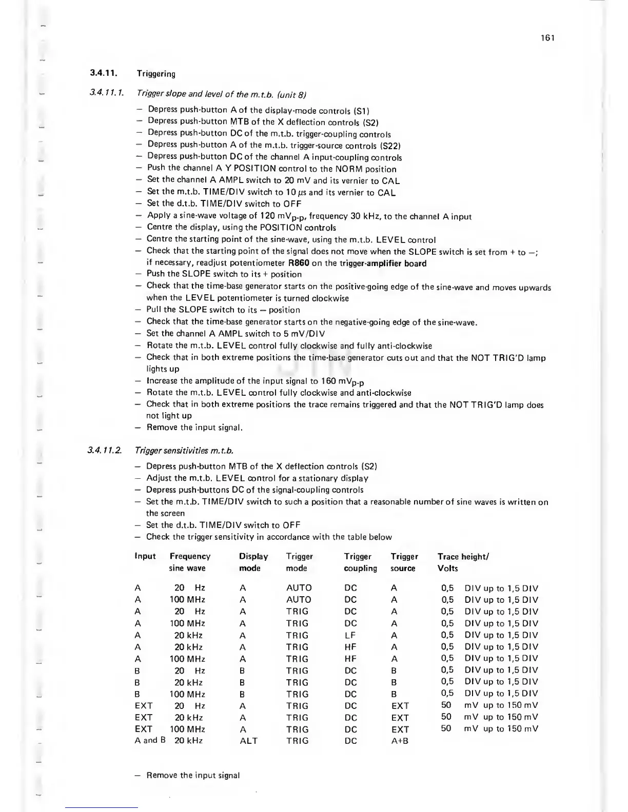
3.4. 1 1.2.
Trigger
sensitivities
m. t.b.
—
Depress
push-button MTB of the
X
deflection
controls
(S2)
—
Adjust the m.t.b.
LEVEL control for
a
stationary display
—
Depress push-buttons DC
of
the signal-coupling controls
—
Set
the
m.t.b.
TIME/DIV
switch
to
such
a
position that
a
reasonable number
of sine waves is written
on
the screen
—
Set
the
d.t.b. TIME/DIV switch
to
OFF
—
Check the trigger sensitivity in
accordance
with the
table below
Input
Frequency Display Trigger
Trigger Trigger
Trace height/
sine wave mode
mode coupling source Volts
A 20 Hz A AUTO DC A
0,5
DIV up
to
1,5
DIV
A 100 MHz
A AUTO DC
A
0,5
DIV
up to
1,5
DIV
A 20
Hz
A TRIC DC A
0,5
DIV up
to
1,5
DIV
A 100 MHz
A TRIC
DC
A
0,5
DIV
up to
1,5
DIV
A 20 kHz A TRIC LF A 0,5
DIV
up to
1,5
DIV
A
20
kHz
A
TRIC
HF
A
0,5
DIV
up to
1,5
DIV
A 100
MHz
A TRIC
HF A
0,5
DIV
up
to
1,5
DIV
B 20 Hz B TRIC DC B
0,5
DIV
up to
1,5
DIV
B
20 kHz B TRIC DC
B
0,5
DIV
up to
1,5
DIV
B 100 MHz
B
TRIC DC B
0,5
DIV
up
to 1,5
DIV
EXT
20
Hz
A TRIC
DC EXT
50 mV
up to 1 50 mV
EXT
20
kHz
A TRIC
DC EXT
50 mV up
to
1
50
mV
EXT
100 MHz A
TRIC DC
EXT
50 mV
up
to
150 mV
A
and
B
20 kHz
ALT
TRIC DC
A-i-B
—
Remove the input
signal
 Loading...

