6.
Operation
GENERAL
When
exercising'
the use of the PM
571
5 or em-
ploying
the generator
in practical set-ups
it is
recommended
to
use
the
Philips
200ps
oscilloscope PM 3400
as displaying unit.
This
oscilloscope enables
error-free presen-
tation of
the 6ns transition time
of the
PM 5715
and high
resolution close-ups of
minor pulse
details. A
conventional oscilloscope
with
slower rise time
can be used,
but at the ex-
pense of the pulse
characteristics.
PULSE
OUT OUTPUT. AMPLITUDE
CONTROL AND DC OFFSET
The PULSE
OUT output
can stand
open
circuit
and short circuit conditions. In
the lowest
am-
plitude ranges,
0.5V, 1.5V
and
5V,
the output is
internally terminated
with 500
.
In
the 10V range,
a
current source
provides
a
maximum
current output of
200mA. Higher
current
can
be
taken out,
however at the
ex-
pense of pulse
amplitude.
If
the
device
under test is not determinated
with 500
,
it is recommended
to
use the Philips
500
terminations
PM
9581,
3W,
or
PM
9585,
1
W,
which are available
as optional
accessories.
Continuous setting
of the pulse amplitude
within each of
the
four ranges
is made with
the
amplitude
VERNIER,
from 0.2V
to
10V.
The DC-OFFSET
control provides
a baseline
shift from +2.5V
to -2.5V. The control
is
mechanically locked in
the zero position,
thus
preventing
any offset voltage
to be introduced
by accident.
The
total sum of d.c.-offset and
pulse amp-
litude is maximum
10V.
Consequently,
at the highest
amplitude
position, d.c.-offset
is added at the expense of
pulse amplitude.
OUTPUTS AUX.
OUT AND SYNC.
OUT
Output AUX. OUT
provides
an
auxiliary
signal at
a fixed amplitude of
+2.5V into
a
50Q
load.
A
high-ohmic load makes
the amplitude increase
to maximum
+4.5V at
open circuit. The AUX.
OUT output is always
connected
to the delay
and
duration
circuits
of
the generator, even in
the T/2
mode,
but
remains unaffected
by the
DC-OFFSET
control, NORM./INV.
and
polarity
("
H
—
")
switches.
The typical
rise time of
the output pulse is
lOns;
typical
fall
time is 5ns. The signal occurs
approximately 12ns
before
the main signal at
the
PULSE
OUT connector and
can be
fed
direc-
tly into TTL circuits.
The output
SYNC.
OUT is connected
to the
in-
ternal
square wave multivibrator or, in the EXT.
position,
to the
trigger circuit.
In
the
internal mode
the
signal
is a
square
wave
with
the
set repetition time but unaffected
by
the set delay, duration or other settings. In
the
EXT.
position, the triggering signal determines
the repetition time and duty cycle of the
SYNC.
OUT signal.
This signal occurs approximately
40ns before
the
main signal
at
the
PULSE
OUT connector
when the
DELAY
control is set
to
10ns.
The amplitude is fixed to
+1.5V
into a
50Q
load
(
+3V
open
circuit).
Typical
rise time
is
10ns; typical
fall
time is 5ns.
The signal can be used
to
trigger external
equipment,
e.g.
an oscilloscope.
RAMP TIME CONTROL,
tr
AND
tf
VERNIERS
The ramp time
can
be set to
6
ranges
with
con-
tinuous and
independent
control of
rise
time
(vernier
tr)
and
fall
time (vernier tf) within each
of
the
ranges.
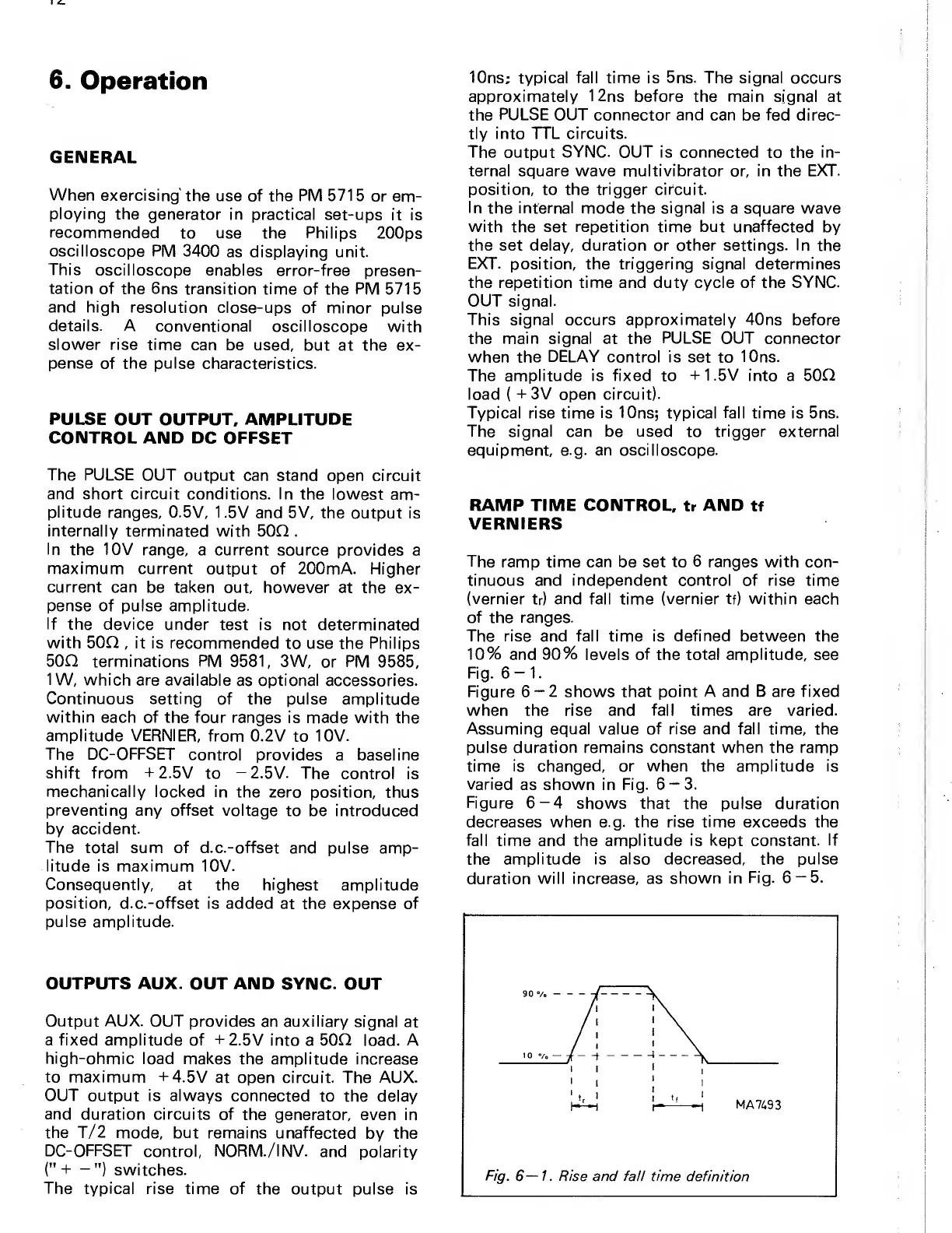
The rise and fall time is defined between
the
10%
and
90%
levels
of
the total amplitude, see
Fig.
6-1.
Figure
6-2
shows that
point A and B are fixed
when the
rise
and
fall times
are varied.
Assuming equal value of rise and fall time,
the
pulse duration remains constant when the ramp
time is changed, or when the amplitude is
varied
as shown in Fig.
6-3.
Figure
6-4
shows that the
pulse duration
decreases when e.g. the
rise time
exceeds the
fall time and
the
amplitude is kept
constant.
If
the
amplitude is also decreased, the pulse
duration will increase, as
shown in
Fig.
6-5.


 To Next Page
 Loading...