B
Fig.
6—2.
Pulse
duration remains
constant at
equal values of rise and fall
time
Fig.
6
—
3. Pulse
duration
remains constant
when the
amplitude
is varied at equal values
of rise and fall
time
5 0
•/,
Fig.
6—4.
Pulse
duration
decreases when the
rise time
exceeds the
fall time (
or
v.v.) at a
constant amplitude
Fig.
6—5.
Pulse
duration decreases
when
varying the amplitude
at
unequal rise and fall
time
SINGLE
PULSE MODE
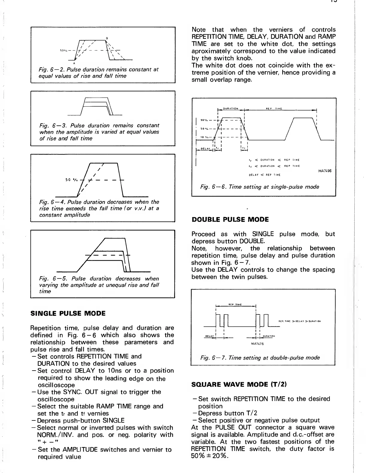
Repetition time,
pulse delay and duration are
defined in
Fig. 6-6 which also shows the
relationship
between these
parameters and
pulse
rise
and fall times.
-Set controls
REPETITION TIME and
DURATION
to the
desired values
-Set control
DELAY
to 10ns
or
to
a position
required
to show
the
leading
edge
on
the
oscilloscope
-Use
the
SYNC. OUT signal to
trigger the
oscilloscope
—
Select the suitable
RAMP TIME
range and
set the
tr
and
tf vernies
-Depress push-button
SINGLE
—
Select normal or
inverted pulses with switch
NORM./INV. and pos.
or
neg.
polarity with
TT
_j_
TT
—
Set
the
AMPLITUDE
switches and vernier
to
required value
Note that when the
verniers of controls
REPETITION TIME, DELAY, DURATION and
RAMP
TIME
are set
to
the white dot, the settings
aproximately correspond to the value
indicated
by the switch knob.
The white dot does not
coincide with
the
ex-
treme position of the
vernier,
hence
providing a
small
overlap range.
DOUBLE PULSE MODE
Proceed as with
SINGLE
pulse
mode, but
depress button
DOUBLE.
Note, however,
the relationship between
repetition time, pulse delay and
pulse duration
shown in
Fig.
6-7.
Use the
DELAY controls
to
change the spacing
between the
twin pulses.
REP. TIME
>D£LAY
>DURATI0N
I
i
,
I
I
Fig.
6—7.
Time setting at
double-pulse mode
SQUARE WAVE
MODE
(T/2)
-Set
switch
REPETITION TIME
to
the
desired
position
-Depress
button
T/2
—
Select positive or
negative pulse
output
At the
PULSE OUT connector a
square
wave
signal is
available. Amplitude
and d.c.-offset
are
variable. At
the
two
fastest positions
of the
REPETITION TIME switch, the duty
factor is
50%
±20%.


 To Next Page
 Loading...