Note
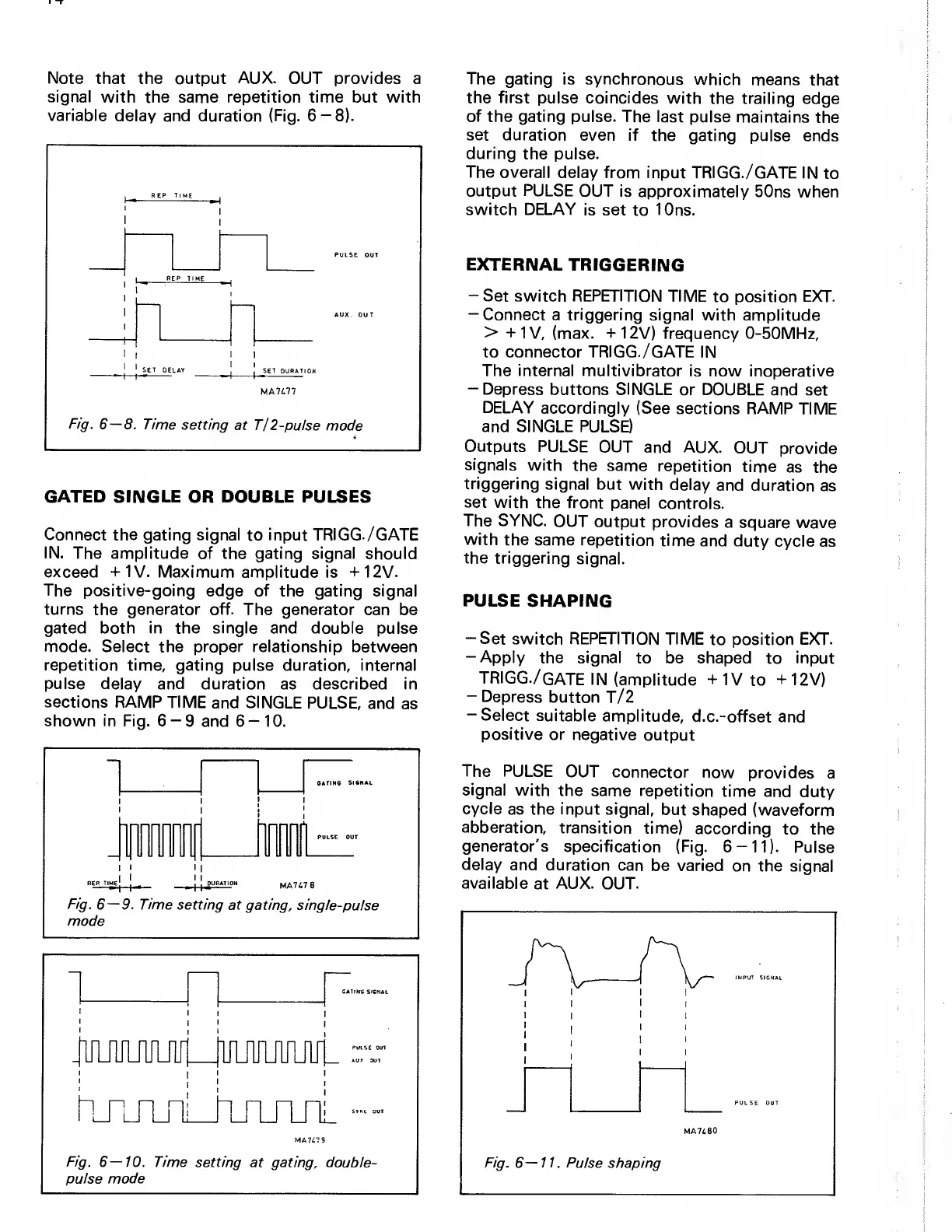
that the output
AUX.
OUT provides a
signal
with the same repetition time but with
variable
delay and duration (Fig.
6-8).
REP TIME
j
PULSE
OUT
1
REP
TIME
},—
^
AUX. OUT
I
1
1
I
( 1
SET DELAY
1
,
SET DURATION
Fig.
6-
MA7477
8. Time
setting
at T/ 2-pulse
mode
GATED SINGLE
OR
DOUBLE PULSES
Connect the gating signal
to
input
TRIGG.
/GATE
IN.
The
amplitude of the gating signal should
exceed
+1V. Maximum amplitude
is +12V.
The positive-going
edge
of
the gating signal
turns
the
generator off.
The
generator
can be
gated both in the single
and
double
pulse
mode.
Select
the proper relationship
between
repetition time,
gating pulse duration, internal
pulse delay and
duration as described in
sections RAMP TIME
and
SINGLE
PULSE,
and
as
shown
in Fig. 6
—
9 and 6
—
10.
I
I
I
I II
RER
th
^e|
I
^URATIOH
MA767 8
Fig.
6—9.
Time
setting at gating,
single-pulse
mode
—
!
GATING SIGNAL
<
1
1
'
i
1
JUUUUlfUlfl
IIIUUIJ
1
1
1
pLTLrbTLiijTj
Fig.
6—10.
Time setting
at
pulse mode
1.
1
IIUIIU
:rr
1
1
1
T_rii_
MA747
9
lating,
double-
The
gating is synchronous
which
means
that
the first
pulse coincides
with
the trailing edge
of
the
gating
pulse. The last
pulse
maintains
the
set duration
even if
the gating pulse
ends
during
the pulse.
The overall
delay from input
TRIGG./GATE IN
to
output
PULSE
OUT is
approximately
50ns when
switch DELAY
is set
to 10ns.
EXTERNAL
TRIGGERING
-Set switch REPETITION TIME
to position
EXT.
-Connect a triggering
signal with amplitude
>
+1V,
(max. +12V) frequency
0-50MHz,
to connector
TRIGG.
/GATE IN
The internal
multivibrator
is now inoperative
-Depress
buttons SINGLE or DOUBLE
and set
DELAY
accordingly (See
sections RAMP
TIME
and SINGLE PULSE)
Outputs PULSE
OUT
and AUX.
OUT
provide
signals
with
the same
repetition
time
as
the
triggering
signal
but with
delay
and duration
as
set
with
the front
panel
controls.
The SYNC.
OUT
output
provides
a square
wave
with
the same
repetition
time
and
duty
cycle as
the triggering
signal.
PULSE
SHAPING
-Set switch REPETITION TIME
to position
EXT.
-Apply
the signal
to be shaped
to
input
TRIGG.
/gate
in
(amplitude
+1V
to +12V)
-Depress
button
T/2
-Select suitable
amplitude,
d.c.-offset
and
positive
or negative
output
The PULSE
OUT
connector
now provides
a
signal
with
the same
repetition
time and
duty
cycle
as the input signal,
but
shaped (waveform
abberation,
transition
time)
according
to the
generator's
specification (Fig.
6-11).
Pulse
delay
and duration
can
be varied
on the signal
available
at
AUX.
OUT.


 To Next Page
 Loading...