SINGLE
SHOT
DUAL CHANNEL
ARRANGEMENT
-Set
switch REPETITION TIME
to position
EXT.
-Set
DURATION
and DELAY
to desired values
-Select
NORMAL
or
INVERTED
mode,
amplitude and d.c.-offset
-Depress the
SINGLE
SHOT button
One
and
only one pulse is now generated
having
a duration
as set with
the
front panel
controls.
Electronic
switching circuits ensure bounce-free
switching.
Outputs
SYNC.
OUT and AUX. OUT also provide
the
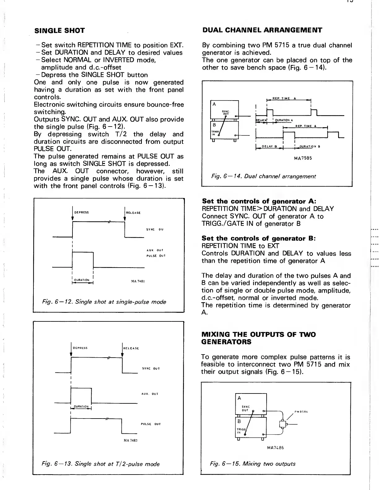
single pulse
(Fig. 6
—
12).
By depressing
switch T/2 the delay and
duration circuits are disconnected
from output
PULSE OUT.
The pulse generated
remains
at
PULSE
OUT as
long
as
switch SINGLE
SHOT is depressed.
The
AUX.
OUT connector,
however, still
provides
a single pulse whose duration is
set
with
the
front
panel controls
(Fig.
6
—
13).
By combining two PM 5715
a
true
dual channel
generator is achieved.
The
one
generator
can be placed on
top
of the
other
to
save
bench space
(Fig. 6
—
14).
j
,
REP. TIME A
^
I
1
I
n
REP. TIME A
I
1
n_
I
DELAY
B
^
1
j
^
DURATIO N
B
MA7585
Fig.
6—14.
Dual channel arrangement
DEPRESS
RELEASE
AUX
OUT
PULSE OUT
t
1
j
DURATION
j
Fig.
6—12.
Single
shot at single-pulse
mode
DEPRESS
RELEASE
t/
SYNC
OUT
I
^
DURATION
j
PULSE OUT
Fig. 6—13.
Single
shot at
T/2-pulse
mode
Set the controls
of generator A:
REPETITION TIME>
DURATION
and
DELAY
Connect SYNC.
OUT of generator A
to
TRIGG. /GATE IN
of generator B
Set the controls
of generator B:
REPETITION TIME
to
EXT
Controls
DURATION
and
DELAY
to
values
less
than the repetition time of
generator A
The
delay and duration of
the two pulses A
and
B
can
be
varied
independently
as well as selec-
tion of single or
double pulse mode,
amplitude,
d.c.-offset, normal
or inverted mode.
The
repetition time is
determined by
generator
A.
MIXING
THE OUTPUTS
OF TWO
GENERATORS
To
generate more complex
pulse patterns
it is
feasible
to interconnect two
PM
5715
and mix
their output signals
(Fig.
6
—
15).
Fig.
6—15.
Mixing
two outputs


 To Next Page
 Loading...