EasyManua.ls Logo

Philips PM 6670 - Frequency Average, Ext. Standard Input Checks; Ext. Reset, Arming, Int. Output, Gate Monitor Checks

Philips PM 6670
21 pages
Print Icon
To Previous Page IconTo Previous Page
Loading...
23
•
Set
the
pulse
width
to
approx
0.4us
and
increase
the
frequency
slowly
until
the
counter
starts
to
display
an
incorrect
pulse
width.
•
Push
SLOPE
for
input
A
and
release
SLOPE
for
input
B.
The
dead-time
should
be
less
than
O.Sps.
•
Release
COM
via
A
and
SLOPE
for
input
A.
Check
of
FREQUENCY
AVERAGE
•
Select
FREQ
A.
•
Set
slide
switch
E
on
the
rear
panel
to
position
FREQ
AVERAGE.
•Connect
a
120MHz
sine-wave
with
50mVpp
ampli
tude
to
input
A.
•
Set
the
measuring
time
to
Is.
The
display
read-out
should
be
120.XXXXX
MHz.
•
Connect
the
signal
below
to
input
E.
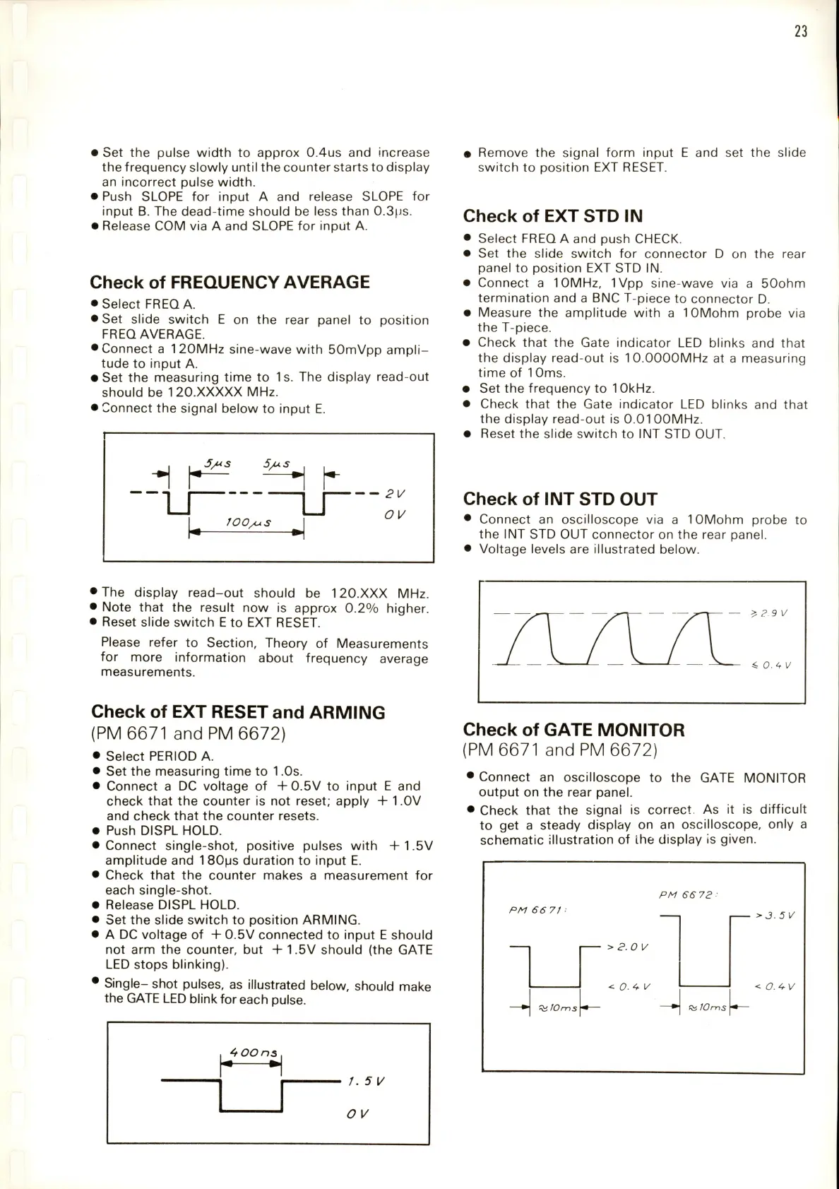
"""L
5/us
JOO/jS
—
OV
Remove
the
signal
form
input
E
and
set
the
slide
switch
to
position
EXT
RESET.
Check
of
EXTSTDIN
•
Select
FREQ
A
and
push
CHECK.
•
Set
the
slide
switch
for
connector
D
on
the
rear
panel
to
position
EXT
STD
IN.
•
Connect
a
10MHz,
IVpp
sine-wave
via
a
50ohm
termination
and
a
BNC
T-piece
to
connector
D.
•
Measure
the
amplitude
with
a
lOMohm
probe
via
the
T-piece.
•
Check
that
the
Gate
indicator
LED
blinks
and
that
the
display
read-out
is
10.0000MHz
at
a
measuring
time
of
10ms.
•
Set
the
frequency
to
10kHz.
•
Check
that
the
Gate
indicator
LED
blinks
and
that
the
display
read-out
is
0.0100MHz.
•
Reset
the
slide
switch
to
INT
STD
OUT.
Check
Of
INT
STD
OUT
•
Connect
an
oscilloscope
via
a
10Mohm
probe
the
INT
STD
OUT
connector
on
the
rear
panel.
•
Voltage
levels
are
illustrated
below.
to
'The
display
read-out
should
be
120.XXX
MHz.
'
Note
that
the
result
now
is
approx
0.2%
higher.
'
Reset
slide
switch
E
to
EXT
RESET.
Please
refer
to
Section,
Theory
of
Measurements
for
more
information
about
frequency
average
measurements.
Check
of
EXT
RESET
and
ARMING
(PM
6671
and
PM
6672)
•
Select
PERIOD
A.
•
Set
the
measuring
time
to
1
.Os.
•
Connect
a
DC
voltage
of
+0.5V
to
input
E
and
check
that
the
counter
is
not
reset;
apply
+
1.0V
and
check
that
the
counter
resets.
•
Push
DISPL
HOLD.
•
Connect
single-shot,
positive
pulses
with
+
1.5V
amplitude
and
1
80ps
duration
to
input
E.
•
Check
that
the
counter
makes
a
measurement
for
each
single-shot.
•
Release
DISPL
HOLD.
•
Set
the
slide
switch
to
position
ARMING.
•
A
DC
voltage
of
+
0.5V
connected
to
input
E
should
not
arm
the
counter,
but
+
1.5V
should
(the
GATE
LED
stops
blinking).
•
Single-
shot
pulses,
as
illustrated
below,
should
make
the
GATE
LED
blink
for
each
pulse.
4
OOns
f.5[/
—
?9V
Check
of
GATE
MONITOR
(PM
6671
and
PM
6672)
•
Connect
an
oscilloscope
to
the
GATE
MONITOR
output
on
the
rear
panel.
•
Check
that
the
signal
is
correct.
As
it
is
difficult
to
get
a
steady
display
on
an
oscilloscope,
only
a
schematic
illustration
of
the
display
is
given.
PM
66
72
:
PM
66
7t
•
>3.5V
>
2.0
V
<
0.
4
1/
<
O.PV
JOms
10ms