Do you have a question about the Philips PMC100 and is the answer not in the manual?
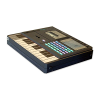
Details synthesizer features like melody/rhythm tracks and chip type.
Specifies tape section bandwidth, distortion, and S/N ratio.
Lists audio and power input connections with their specifications.
Details power requirements, including battery and AC adapter specs.
Lists power consumption for synthesizer and tape sections.
Provides battery life estimates for different modes of operation.
Specifies the physical dimensions of the device.
States the weight of the device excluding batteries.
Details the RAM test procedure and expected 'Err' message.
Describes the LCD segment test and interaction required.
Describes the procedure for testing all keys on the keyboard.
Details tests for drum sounds and synthesized tones.
Explains the procedure for testing tape loading and data transfer.
Details adjustment for tape speed using a wow and flutter meter.
Specifies azimuth adjustment for the record/playback head.
Outlines the bias frequency measurement and adjustment.
Describes how to measure and adjust bias amplitude.
A schematic diagram illustrating the digital logic circuits.
A schematic diagram detailing the cassette tape mechanism circuit.
Displays pulse waveforms for signals A0 through A15.
Displays pulse waveforms for signals D0 through D7.
Shows clock, AS, and E signal waveforms and their timing.
| Polyphony | 16 voices |
|---|---|
| Effects | Reverb, Chorus, Delay |
| Type | Digital |
| Filter | Digital |
| Keyboard | 61 keys |
| Memory | 64 presets |
| Outputs | Stereo (L/R), Headphones |
| MIDI | In/Out/Thru |