2) Strip about 15 mm of the insulation from the ends of the wires. If the wires are stranded, twist
the strands to avoid frayed conductors.
3) Align the lengths of the wires to be connected. Insert the wires fully into the connector.
4) Use the crimping tool to crimp the metal sleeve at the center position. Be sure to crimp fully to
the complete closure of the tool.
L. When connecting or disconnecting the VCR connectors, first, disconnect the ac plug from the ac
supply socket.
SAFETY CHECK AFTER SERVICING
Examine the area surrounding the repaired location for damage or deterioration. Observe that screws,
parts and wires have been returned to original positions. Afterwards, perform the following tests and
confirm the specified values in order to verify compliance with safety standards.
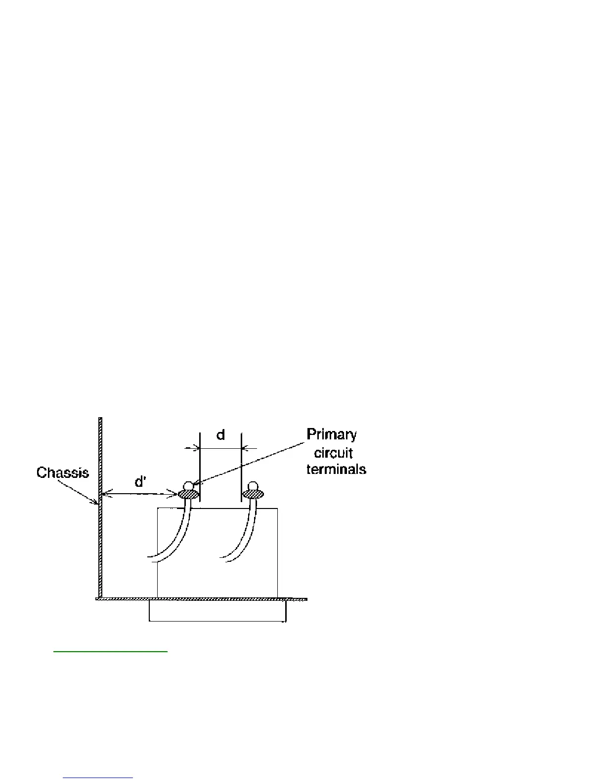
1. Clearance Distance
When replacing primary circuit components, confirm specified clearance distance (d) and (d') between
soldered terminals, and between terminals and surrounding metallic parts. (See graphic bllow)
Table 1 : Ratings for selected area
AC Line Voltage Region Clearance Distance
(d) (d')
USA or > 3.2 mm
110 to 130 V CANADA (0.126 inches)
Note: This table is unofficial and for reference only. Be sure to confirm the precise values.
2. LEAKAGE CURRENT CHECKS