3-5
3.6 PAL/SECAM CONVERTER CIRCUIT
Note:
• Unless otherwise specified in this P/S Converter cir-
cuit adjustments, all measuring points and adjustment
parts are located on the P/S Converter board.
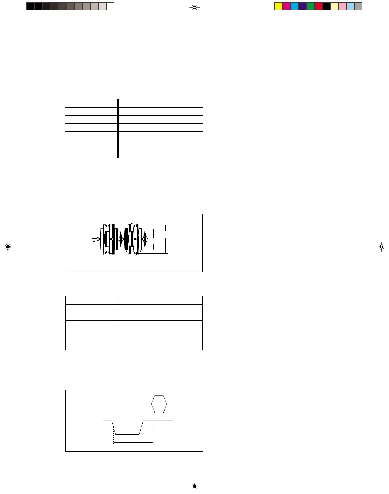
Fig. 3-6-2 PAL burst position
Colour burst signal
H-SYNC
H.rate
C
(Converted colour)
Y
Specified value (G)
3.6.2 SECAM burst position
(1) Observe the waveforms appeared at the measuring
points (D1) and (D2).
(2) Adjust the adjustment part (F) so that the waveforms tim-
ing width between the H-SYNC and the colour burst sig-
nal becomes the specified value (G).
Signal (A1) • Color (colour) bar signal [SECAM]
Mode (B) • EE
Equipment (C) • Oscilloscope
Measuring point (D1) • CN1601 Pin 7
(D2) • CN1601 Pin 3
Adjustment part (F) • VR1603
Specified value (G) • T = 5.6 ± 0.1 µsec
3.6.1 Colour difference level
(1) Observe the C (converted colour) waveform at the meas-
uring point (D).
(2) Adjust the adjustment part (F1) so that the higher level
of the Yellow and Blue of the C waveform becomes the
specified value (G1).
(3) Adjust the adjustment part (F2) so that the higher level
of the Green and Magenta of the C waveform becomes
the specified value (G2).
Signal (A1) • Color (colour) bar signal [SECAM]
Mode (B) • EE
Equipment (C) • Oscilloscope
Measuring point (D) • CN1601 Pin 7
Adjustment part (F1) • VR1602 (B-Y ADJ)
(F2) • VR1601 (R-Y ADJ)
Specified value (G1) • 460 ± 20 mVp-p : VR3506 (B-Y)
(G2) • 620 ± 20 mVp-p : VR3505 (R-Y)
GREEN
H.rate
YELLOW
BLUE
MAGENTA
Specified
value (G2)
Specified
value (G1)
Fig. 3-6-1 Colour difference level
www.freeservicemanuals.info
Digitized in Heiloo the Netherlands