26
4. USAGE AND OPERATION
Refrigerant temp. before
tube inlet too low
Compressor exhaust
temp. too high
Temp. sensor before
tube failure
Tube outlet temp.
sensor failure
Refrigerant temp. too
low from tube outlet
Refrigerant leakage
Unit stops
and alarm
Increase refrigerant
Check through the refrigerant
system
Compressor exhaust
temp.too high
Check through the pressure
switch and return system
High pressure
switch action
Current through
compressor too heavy
Check through the power supply
for compressor or short circuit
Temp. Sensor open
or short circuit
Check and renew the sensor
Temp. Sensor open
or short circuit
Temp. Sensor open
or short circuit
Unit stops
and alarm
Unit stops
and alarm
Unit stops
and alarm
Unit stops
and alarm
Unit stops
and alarm
Unit stops
and alarm
Unit stops
and alarm
Yes
Yes
Yes
Yes
Yes
Yes
Yes
Check and renew the sensor
Check and renew the sensor
Power supply
wrong connection
Wrong connection
or lack of connection
Unit stops
and alarm
Yes
Check the connections
Check through the pressure
switch and return system
Low pressure
switch action
Unit stops
and alarm
Yes
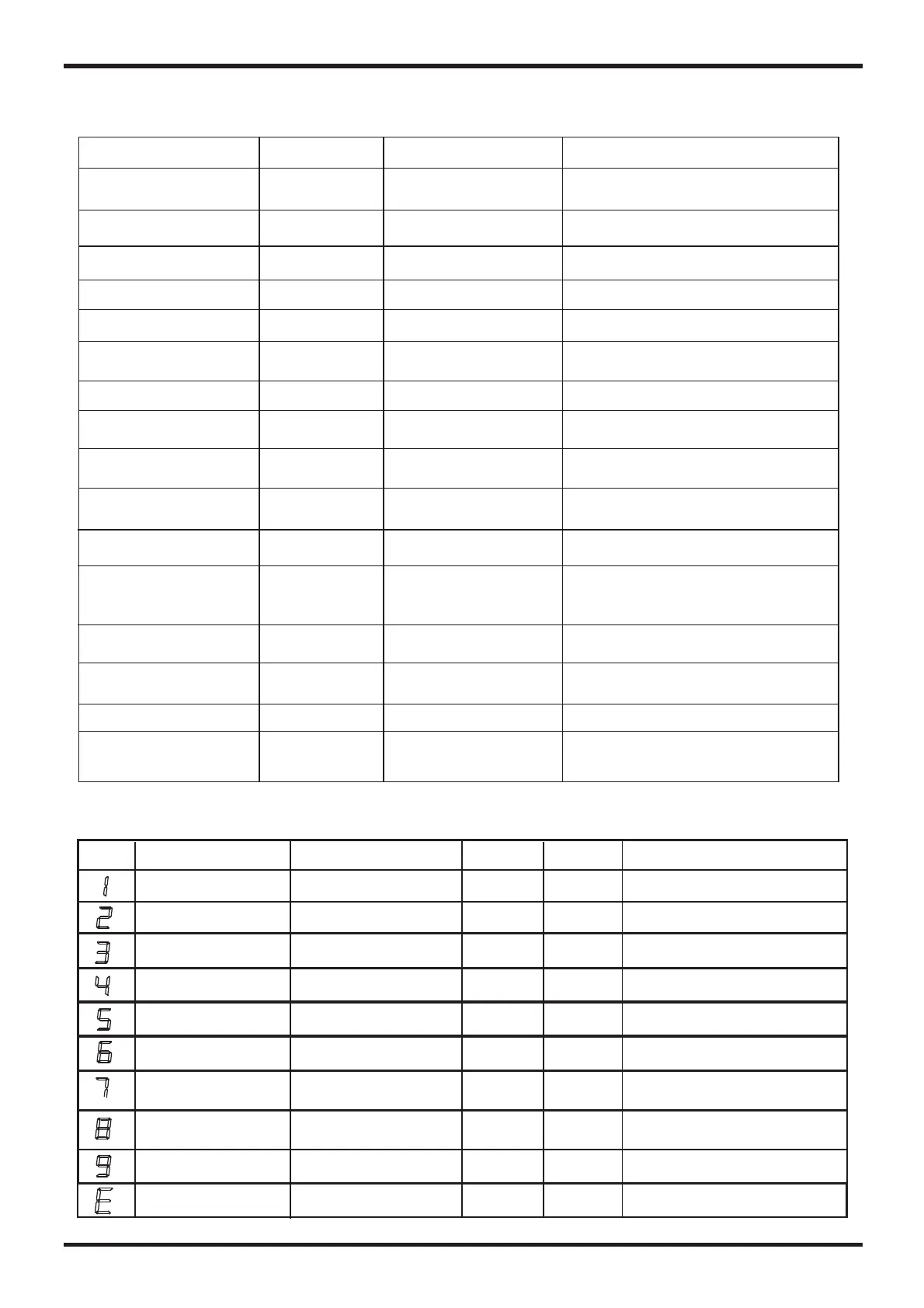
2 You can judge and remove the malfunctions according to the malfunction code display
on the PROTECT 300
Display
Name
Reason
Action
Recover
(yes or no)
Revolution
Refrigerant freezing
High pressure
Exhaust temp.
sensor failure
Yes
Reduce refrigerant
Over-current
on compressor
Low pressure
4. 4 Malfunction table
1. You could determine or remove failures according to the following malfunction table:
Water In Temp Failure
Pipe Temp 2 Failure
Temp Difference
Protect
Systems 1 Failure
Water Out Temp Failure
Ambient Temp Failure
Frostbite 1 Protect
Systems 2 Failure
Temp Differerce
Error
Defrosting
Power Phase
Pipe Temp 2 Failure
Frostbite 2 Protect
Water Flow Failure
Communication
Failure
Malfunction
PP1
PP2
PP3
PP4
PP5
PP6
PP7
PP7
PP7
EE1
EE2
EE5
EE8
Power supply connection
failure
Check the power supply connection.
EE4
Flashing
EE3
System protection failure
of system 1
Check all the protection devices of
system 1.
System protection failure
of system 2
Check all the protection devices of
system 2.
Temp. Sensor is open or
Short circuit.
Check or the water inlet
temp. Sensor.
replace
Temp. Sensor is open or
Short circuit.
Check or the water
outlet temp. Sensor.
replace
Temp. Sensor is open or
Short circuit.
Temp. Sensor is open or
Short circuit.
Check or the 1temp.
Sensor.
replace Coil
Check or the 2temp.
Sensor.
replace Coil
Temp. Sensor is open or
Short circuit.
Check or the ambient
temp. Sensor.
replace
Outlet water
temperature is too low.
Check the flow volume to see
whether it meets the requirements.
Outlet water
temperature is too low.
Check the flow volume to see
whether it meets the requirements.
Ambient temperature
is too low.
Ambient temperature
is too low.
1. Water flow volume is
not enough.
2.No water in water loop.
Check the flow volume to see the
water system is block or not.
Outlet water
temperature is too low.
Check the flow volume to see
whether it meets the requirements.
Communication failure
between remote wire
controller and main board
Check the wire connection between
remote wire controller and main board.
Reason
Solution
LED Display
Anti freezing
under cooling mode
 Loading...