1.2 Setting up your MPS as a DC load switch with deep-discharge protection
Please be sure to always follow this procedure in the following sequence:
Set the DIP switches according to the load switch function
Mount MPS on DIN rail or wall
Connect the load wiring to the unit with proper polarity.
Connect the battery wiring to the unit with proper polarity.
When disassembling perform the installation sequence in reverse order.
Note: Changes to DIP switches after connecting the unit to the battery do not affect the function
of the unit.
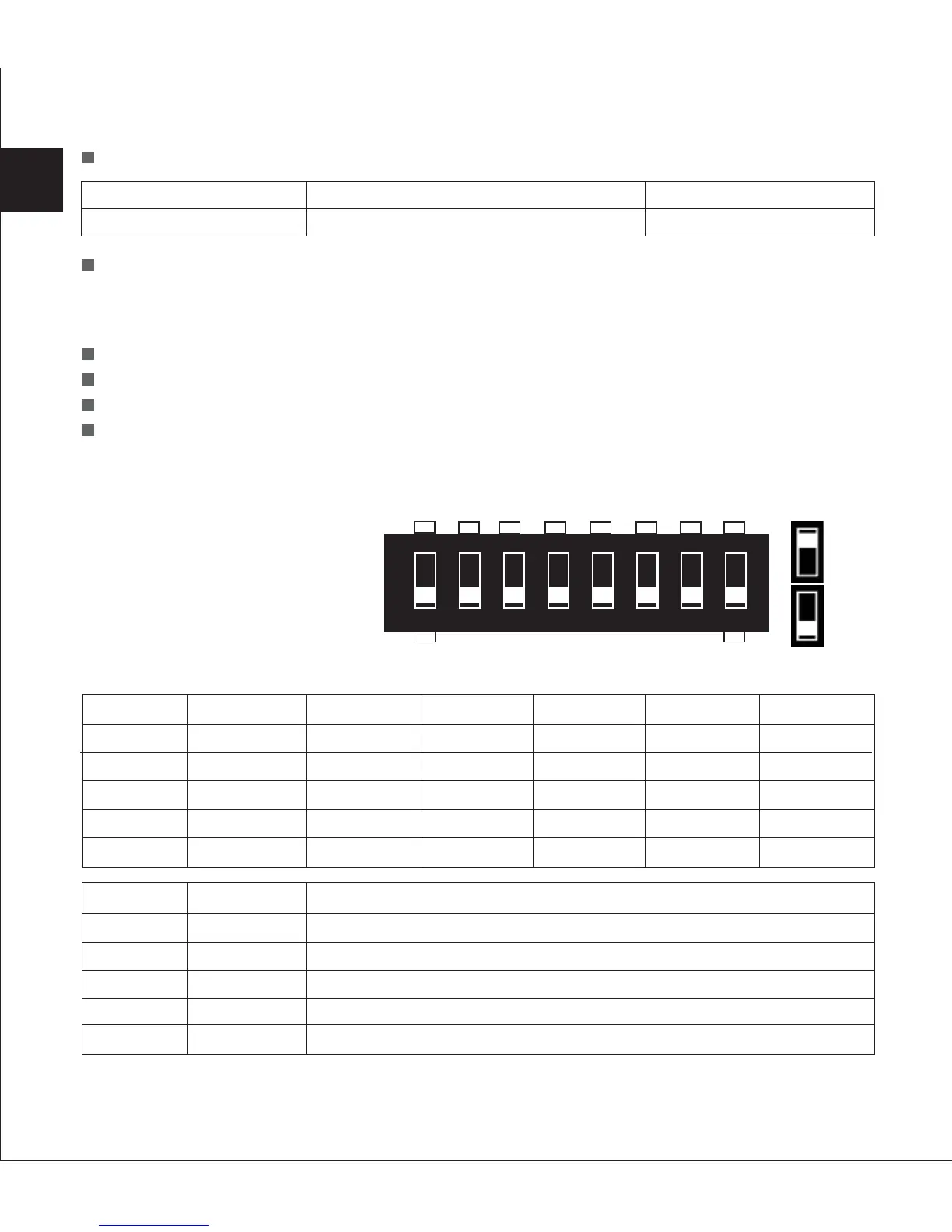
1.2.1 Set-up DIP Switches
The MPS comes with an eight
pole DIP-switch, which can be
used to set up your MPS.
Adjust the DIP switch settings according to load switch function:
Three-LED Status Display
Manual Setting by DIP Switches
28
Yellow LED
MPS on
Green LED
MPS power switch is on
Red LED
Failure
Setting
OFF
X
X
OFF
X
Function
Activates MPS as load switch/deep discharge protection
Unused
Unused
Stand-alone function
Unused
DIP NO.
DIP 8
DIP 7
DIP 6
DIP 5
DIP 4
12 V system
11.0 V
11.25 V
11.5 V
11.75 V
12.0 V
DIP1
OFF
ON
OFF
ON
X
DIP2
OFF
OFF
ON
ON
X
DIP3
OFF
OFF
OFF
OFF
ON
EN
LVD level
Level1
Level2
Level3
Level4
Level5
24 V system
22.0 V
22.5 V
23.0 V
23.5 V
24.0 V
48 V system
44.0 V
45.0 V
46.0 V
47.0 V
48.0 V
+
-
12345678
SAB
ON
OFF
 Loading...