40
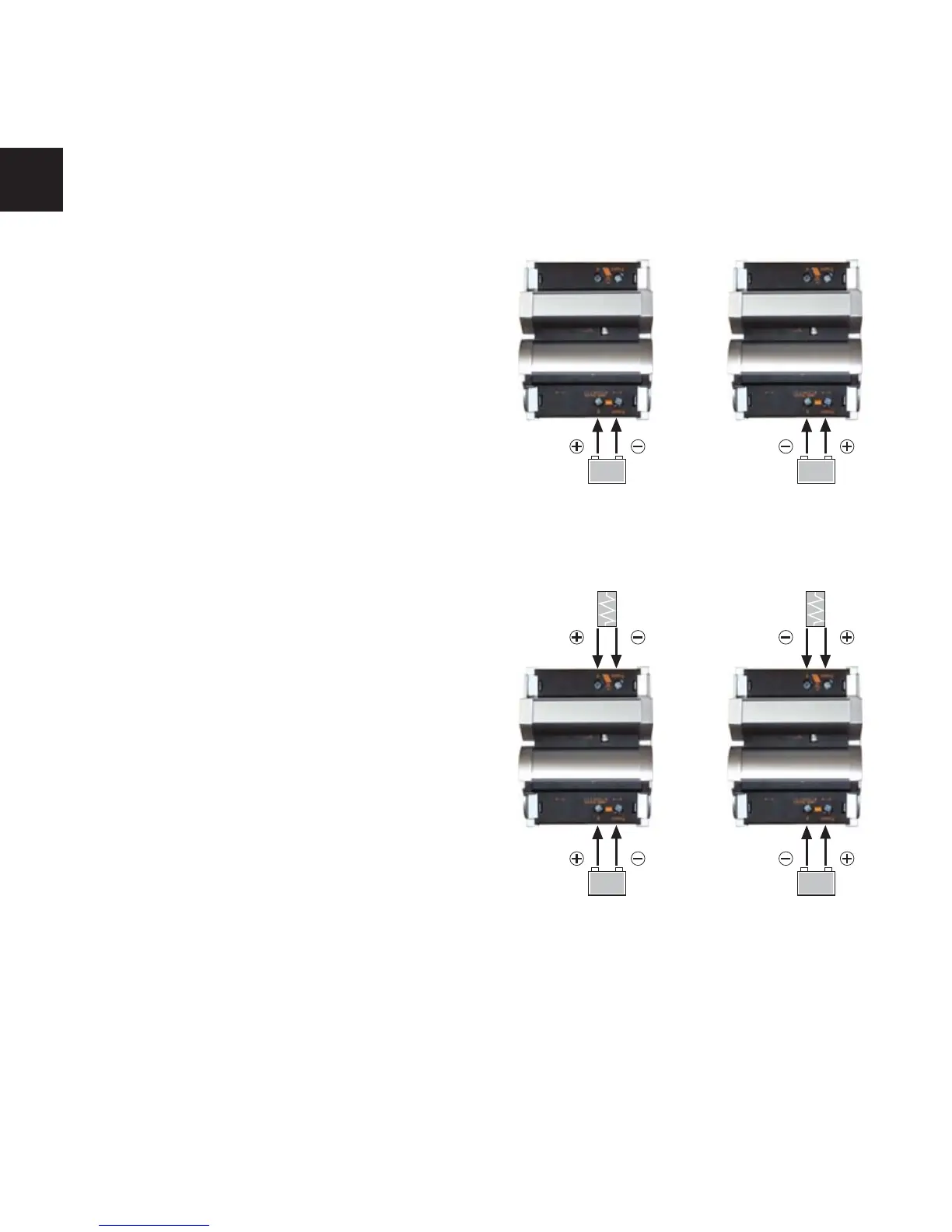
3.3.4 Connecting the Diversion Load
Open the cover at the load terminals. Connect
the wires leading to the diversion load with the
correct polarity. Respect the different wiring
for negative and positive grounded systems.
Wire size: See "Table of recommended wiring
for MPS units" on page 3.
Close the covers.
Positive groundedNegative grounded
3.4 Starting up the Controller
After double-checking of all wires and terminals
insert battery fuse.
3.4.1 Self Test
As soon as battery voltage is applied to MPS, the unit begins a self test routine and wiring-
check. If system passes wiring-check, the LED display changes to "normal operation".
for safety considerations. Insert the fuse after you have connected all wires including the load
and make sure that all terminals are fixed tightly with proper polarity.
Negative grounded Positive grounded
Open the cover on the battery terminal side.
Connect the wires leading to the battery with
the proper polarity.
Mind the recommended wire length (See "Table
of recommended wiring for MPS units" on page
3.). MPS terminals can connect up to 35 mm
2
wire (AWG#2).
Wire size: See "Table of recommended wiring
for MPS units" on page 3.
Close the covers.
Dump
load
Dump
load
EN
 Loading...