Do you have a question about the Phoenix Contact EMpro EEM-MB370 and is the answer not in the manual?
Defines the scope and limitations for the product's installation and operation.
Provides essential safety instructions, warnings, and precautions for safe operation.
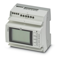
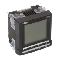
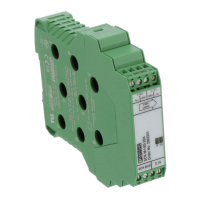
Provides a general overview of the EMpro energy measuring devices and their functionalities.
Covers the electrical installation of the device, including safety precautions and wiring.
Illustrates and describes the pin assignments for current transformer and other connections.
Details the pin assignments for devices using Rogowski coils for current measurement.
Defines and illustrates various network configurations (grid types) supported by the device.
Illustrates network configurations specifically for Rogowski coil current sensors.
Guides through the initial setup process using the device's front panel controls.
Explains how to configure network parameters such as IP address and subnet mask.
Guides the user through configuring IPv4 network settings for the device.
Describes how to select the appropriate grid type for the electrical system.
Covers the configuration of current input settings for devices using current transformers.
Details current input configuration for Rogowski coil setups via the web interface.
Explains how to configure the voltage input parameters of the device.
Describes the process of setting a personal identification number (PIN) for device security.
Explains how to activate the previously set personal identification number (PIN).
Outlines the process for performing initial device configuration using the integrated web server.
Details network configuration steps performed through the device's web interface.
Guides on selecting the correct grid type via the web interface for system compatibility.
Explains how to configure current input settings for current transformer setups via web.
Details current input configuration for Rogowski coil setups via the web interface.
Describes configuring the voltage input parameters through the web server.
Details the process of manually setting the date and time via the web server interface.
Explains how to synchronize the device's clock with an SNTP server for accurate timekeeping.
Provides instructions for resetting the device to its original factory default settings.
Explains how to configure the device using its front panel control buttons.
Details how to perform all device configurations using the integrated web server.
Describes how to use the Modbus communication interface for device configuration.
Covers procedures for managing device access, including PIN and password settings.
Explains how to change or deactivate the device's PIN for access control via the display.
Details how to modify access passwords and user management settings through the web server.
Covers methods for exporting, importing, and transferring configuration data between devices.
Guides on how to export the device's current configuration settings.
Details the process of loading previously exported configuration settings onto the device.
Explains how to directly transfer configuration data from one device to another.
Describes the functions and compliance of the digital input interface (IEC 61131-2 Type 3).
Covers the process of updating the device's firmware to benefit from new features and fixes.
Explains the Modbus protocol, its function codes, and differences between Modbus/TCP and Modbus/RTU.
Covers the steps for integrating EMpro devices into a PROFINET network.
| Product Type | Energy Meter |
|---|---|
| Measurement Parameters | Voltage, Current, Power, Energy |
| Display | LCD |
| Weight | Approx. 300 g |
| Protection Class | IP20 |
| Measurement Category | CAT III 600V |
| Accuracy Voltage | ±0.5% of reading |
| Accuracy Current | ±0.5% of reading |
| Accuracy Power | ±1% |
| Communication Interface | Modbus RTU |
| Dimensions | 96 x 96 x 60 mm |
| Mounting Type | Panel mounting |
| Number of Phases | 3-phase |
| Supply Voltage | 24 V DC |