Do you have a question about the Phoenix Contact FL IL 24 BK and is the answer not in the manual?
Hardware and Firmware User Manual for FL IL 24 BK/FL IL 24 BK-PAC Ethernet/Inline Bus Coupler.
Defines the meaning of symbols used throughout the manual for clarity.
Covers copyright protection, technical changes, and liability disclaimers.
Highlights warnings for SELV operation, ESD, shielding, and housing access.
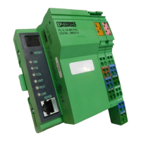
Provides an overview of the bus coupler's capabilities and features.
Details the physical components and interfaces of the bus coupler.
Explains voltage connection, potential jumpers, and connector details.
Explains basic module structure, connector types, and function labeling.
Describes how modules are color-coded for function identification.
Explains the internal potential routing system and data flow.
Details internal circuits, voltage provisions, and the voltage concept.
Provides instructions for installing and removing modules and cables.
Explains how to provide the necessary supply voltage for the system.
Details default device settings and the sequence during firmware startup.
Describes methods for assigning IP addresses via Factory Manager or BootP.
Covers manual details and the software architecture of the driver.
Explains the Device Driver Interface (DDI) functions for bus coupler interaction.
Lists services available in both operating modes and expert mode.
Details services for controlling and parameterizing the controller board.
Explains parameter data transmission via the Peripherals Communication Protocol (PCP).
Lists the supported PCP commands used for device communication.
Describes Modbus connections, port, conformance classes, and message format.
Lists the Modbus function codes supported by the bus coupler.
Maps Modbus tables to the internal FL IL 24 BK(-PAC) tables for data access.
Provides general technical specifications like housing, temperature, and protection.
Details specifications for 24 V main, segment, and bus coupler supplies.
| Number of Channels | 1 |
|---|---|
| Input Voltage | 24 V DC |
| Nominal Input Voltage | 24 V DC |
| Connection Technology | Screw connection |
| Mounting Type | DIN rail |
| Input Voltage Range | 19.2 V DC ... 30 V DC |
| Connection Method | Screw connection |
| Category | Interface module |
| Current Consumption | typ. 3 mA (at 24 V DC) |