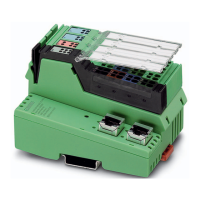
Do you have a question about the Phoenix Contact IL ETH BK DI8 DO4 2TX-PAC and is the answer not in the manual?
| Number of Digital Inputs | 8 |
|---|---|
| Number of Digital Outputs | 4 |
| Ethernet Ports | 2 |
| Transmission Speed | 10/100 Mbps |
| Protocol | Ethernet/IP, Modbus TCP |
| Power Supply | 24 V DC |
| Mounting Type | DIN Rail |
Details connecting the bus coupler via RJ45 connector, noting autocrossing and shielding considerations.
Illustrates a typical connection setup for power and data lines to the bus coupler.
Procedure to restart the bus coupler during operation, affecting outputs but not input image.
Guide to restoring factory default settings for IP, firmware update, and system identification.
Details the LED sequence during firmware startup, including BootP, boot loader, and ready states.
Describes initial startup behavior with BootP requests and how restarts manage existing configuration data.
Enables local module startup without a host; status is retained. Outputs are not enabled until deactivated.
Allows manual setting to 'RUN' state; bus does not start automatically. Requires specific firmware commands.
Activates data transmission after controller write access or 'Clear Net Fail', showing 'ACTIVE' status initially.
Visualizes startup sequences for normal mode and Plug and Play with Expert mode deactivated.
Defines how the bus coupler reacts to errors, choosing between output reset, holding last state, or default values.
Supports up to eight simultaneous Modbus/TCP connections and simultaneous access to different addresses.
Adheres to standard port 502 for Modbus communication via the bus coupler.
Indicates support for Modbus conformance class 0.
Lists function codes FC3, FC4, FC6, FC16, and FC23 for reading and writing registers and data.
Provides status bits for the bus coupler, indicating errors or normal operation states.
Details local bus status bits, including peripheral faults and bus errors.
Contains additional error code information for local bus diagnostics.
Configures Modbus/TCP connection monitoring timeouts for detecting network or client errors.
Provides access to local bus configuration data, including device count, length codes, and module IDs.
Enables or disables delayed start data transfer on the local bus.
Activates or deactivates on-board inputs and outputs.
Provides read-only access to essential module information like firmware version, serial number, and vendor.
Lists services for node management, data access, and message handling through the DDI.
Provides services for managing communication timeouts and Net Fail status for network connections.
Services to activate and deactivate process data monitoring functions via the DDI.
Explains PCP data exchange, including parameter data division, recombination, and protocol functions.
Lists PCP commands like Initiate_Request and Read_Request accessible via the DDI MXI interface.
Describes how to configure the standard PDU size for Inline device communication.
Provides access to static/dynamic information and configuration changes via a web server, protected by password.
Details the process for updating bus coupler firmware using TFTP or FTP, initiated via web-based management.
Allows accessing process data from connected terminals through a web page in XML format.
Defines the structure of XML files, including mandatory elements for station and bus terminal data.
 Loading...