Do you have a question about the Phoenix Contact ILC 131 ETH and is the answer not in the manual?
Explains the main objective of the user manual for starting up and operating Inline controllers.
Lists the necessary hardware and software versions for using the Inline controllers with PC Worx/Express.
Provides essential safety rules and regulations to observe during installation and operation.
Defines the scope and applications for which the Inline controller is designed.
Instructs on the proper and environmentally sound disposal of the device.
Provides an overview of the Inline controller's features, capabilities, and differences between models like memory size.
Details application scenarios for ILC 131/151 ETH/XC and ILC 171/191 ETH 2TX models in Ethernet and INTERBUS systems.
Explains how to integrate the Inline controller as a PROFINET device within a PROFINET network using PC Worx software.
Describes setting up applicative system redundancy for ILC 171 ETH 2TX or ILC 191 ETH 2TX controllers in a PROFINET network.
Outlines specific precautions and requirements for using the controller safely in potentially explosive environments (Zone 2).
Provides instructions on how to safely unpack the Inline controller, including essential ESD precautions.
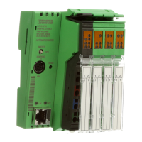
Identifies and explains the purpose of all physical connection and operating elements visible on the controller's exterior.
Explains the meaning of various LEDs and indicators used for local error diagnostics and monitoring the controller's operational status.
Details the function of the mode selector switch for defining the controller's operating state (RUN, STOP, MRESET).
Describes the location and function of the concealed reset button for resetting the controller to its default settings.
Explains the use of parameterization memory, including integrated and plug-in SD card options for saving data.
Provides step-by-step instructions for safely inserting and removing the parameterization memory (SD card) using push/push technology.
Presents a schematic diagram illustrating the internal electrical structure and isolated areas of the Inline controller.
Details the procedures and considerations for mounting and removing the Inline controller from a DIN rail, including terminal compatibility.
Outlines the available communication interfaces and paths for connecting and communicating with the Inline controller via Ethernet and PRG.
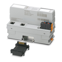
Describes the Ethernet interface, its connection via RJ45 sockets, and pin assignments for network connectivity.
Explains the serial interface for connecting to a PC, its limitations for programming, and assembly instructions for the connecting cable.
Details the function blocks available in PC Worx for utilizing the serial PRG interface for parameter assignment and I/O communication.
Covers INTERBUS communication, including local bus creation, remote bus connections, and supported functions.
Provides information on power supply requirements, including sizing, connection methods, and voltage ranges for the Inline controller.
Guides on selecting an appropriate power supply unit based on application currents, controller requirements, and overload characteristics.
Outlines the step-by-step procedure for connecting external 24 V DC power supplies to the Inline controller and initialisation indicators.
Explains the provision and characteristics of the 24 V segment and main supplies, including jumpering options for isolation.
Describes the digital inputs and outputs, their assignment, and wiring for connecting sensors and actuators to the controller.
Specifies the minimum required versions of PC Worx/PC Worx Express and controller firmware for compatibility.
Guides on creating a new project in PC Worx/Express, including template selection and project information setup.
Details methods for assigning an IP address to the controller, including DCP protocol and BootP server configuration.
Explains the process of activating and integrating the Inline controller as a PROFINET device in a PC Worx project.
Describes how to set the internal system clock (time and date) of the Inline controller using PC Worx Express settings.
Explains the function for downloading changes to the controller, including version compatibility information.
Covers the functions of the plug-in parameterization memory (SD card) for main or additional memory usage and data storage.
Details the use of the SD card as additional memory and its implications for storing application-specific data.
Explains how to use the SD card as a storage medium for log files, including directory creation and FTP access.
Describes how to access and manage files on the parameterization memory using Internet Explorer via FTP.
Explains how to enable the FTP folder view functionality within Internet Explorer settings for accessing the controller's memory.
Details how to activate or deactivate the FTP server for enhanced security and access control to the controller.
Guides on setting up usernames and passwords to restrict unauthorized FTP access to the parameterization memory.
Explains how to enable or disable the HTTP server (web server) for remote access and security configuration.
Describes how to configure and use HTTPS for secure HTTP server communication with the controller, enhancing security.
Explains the use of the SMTPS method for secure email transmission from the controller, requiring an IT library function block.
Details how to enable or disable specific network ports (e.g., 7, 1962, 41100) for security and application requirements.
Explains how to activate or deactivate the journaling function to protect the file system integrity during voltage failures.
Describes how to enable or disable the Media Redundancy Protocol (MRP) client function for network redundancy in specific controllers.
Lists and describes function blocks used for accessing and managing files on the parameterization memory from within an application program.
Details function blocks enabling IEC 61131-5 compliant Ethernet communication between controllers and devices via TCP/IP or UDP/IP.
Lists function blocks for establishing PCP communication between the Inline controller and INTERBUS devices, including connection limits.
Explains data alignment in memory, the creation of data gaps, and methods to manage them for correct data transmission.
Introduces special program functions and system variables for diagnostics and control of the bus system using PC Worx/Express.
Lists system variables for reading the states of local digital inputs and writing to local digital outputs.
Explains the diagnostic status register, which stores controller operating states and error information for each bit.
Provides additional information on errors indicated in the status register, including error location, code, and special interface error handling.
Lists PROFINET-specific system variables for monitoring the status of the higher-level PROFINET controller and the PROFINET device.
Details system variables related to the IEC 61131 runtime system, such as PLC mode, task status, and error counts.
Lists system variables that display the operational status of the control processor, including runtime errors and loading states.
Describes system variables related to the controller's power storage for the realtime clock and the validity of its data.
Lists system variables indicating the operational status (OK) of the main, input, and output power supplies.
Lists system variables reflecting the current position of the mode selector switch on the controller (MRESET, STOP, RUN_PROG).
Details system variables for accessing and displaying the current system time components (hours, minutes, seconds, day, month, year).
Presents comprehensive technical specifications for the Inline controller, including dimensions, weight, connection data, and environmental ratings.
Lists the available Inline controller modules with their corresponding order numbers and packaging quantities.
Lists the order numbers and details for essential accessories required for the Inline controller system setup and operation.
Provides ordering information for the PC Worx and PC Worx Express automation software required for controller programming.
Lists available user manuals, application notes, and quick start guides for the Inline controller and associated software.
Provides a table of common installation errors, their potential causes, and recommended remedies for troubleshooting.
Explains the procedure for updating the controller's firmware via Ethernet for product improvement and new functions.
Details the method for connecting I/O devices and supply voltage using unshielded cables and spring-cage terminals.
Presents derating curves and specifications for current and power dissipation under various ambient temperatures.
Summarizes successful testing of controllers under extreme ambient temperature change cycles according to IEC 61131-2.
Provides a comprehensive list of all figures included in the manual, with their corresponding titles and page numbers.
Offers a complete listing of all tables presented in the manual, including their titles and page numbers.
| Product Type | Inline Controller |
|---|---|
| Model | ILC 131 ETH |
| Digital Inputs | 8 |
| Digital Outputs | 8 |
| Analog Outputs | 2 |
| Communication Interface | Ethernet |
| Ethernet Ports | 1 |
| Power Supply Voltage | 24 V DC |
| Protocols | Modbus TCP |
| Operating Temperature Range | -25 °C ... 55 °C |