Do you have a question about the Phoenix Contact AXL F BK PN and is the answer not in the manual?
| Category | Industrial Electrical |
|---|---|
| Manufacturer | Phoenix Contact |
| Number of supported I/O modules | 63 |
| Protocols supported | PROFINET |
| Degree of Protection | IP20 |
| Operating Voltage/Input Voltage | 24 V DC |
| Rated Voltage | 24 V DC |
| Product Type | Bus Coupler |
| Connection Technology/Method | Push-in connection |
| Current consumption | typ. 70 mA (at 24 V DC) |
| Housing Material | Polyamide |
| Operating Temperature | -25 °C ... 60 °C |
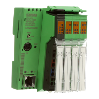
Lists the key features of the Axioline F bus coupler for PROFINET, including connectivity, cycle times, and supported protocols.
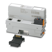
Details product ordering codes for accessories like connectors and marking, along with required user manuals.
Provides physical dimensions, color, weight, and ambient operating conditions for the bus coupler.
Details connection methods, conductor cross-sections, and interface specifications for PROFINET and local bus.
Outlines system limits, supported protocols, and power supply requirements including voltage range and consumption.
Covers mechanical test results, EMC directive conformance, noise immunity, and product approvals.
Illustrates the internal wiring and provides a key for understanding the functional components and connections.
Explains how to connect the PROFINET network to the bus coupler using an 8-pos. RJ45 connector.
Details the terminal point assignment for connecting the supply voltage, including pin and color coding.
Provides a visual example of how to connect the Ethernet and power supply cables to the bus coupler.
Describes the meaning and states of the UL, BF, SF, and RDY LEDs for operational status and errors.
Explains the meaning and states of the D (Diagnostics) and E (Error) LEDs for detailed status information.
Details LED states for PROFINET communication during normal operation and firmware update processes.
Lists LED indicators in error states, their meanings, and recommended measures or troubleshooting steps.
Explains how PROFINET stores and transmits diagnostic information and error types.
Describes the default settings and initial states of LEDs upon device startup or reset.
Details the reset button's functions for restarting the coupler or restoring default settings, including LED indications.
Explains the purpose of the service interface for diagnostics, parameterization, and I/O testing.
Covers parameterization using PC Worx, GSDML files, and other PROFINET controller tools.
Explains how devices can be replaced in the PROFINET network without reconfiguring the station name or address.
Describes how PRL enables redundant systems with two PROFINET controllers and conditions for its use.
Explains the 'Dynamic configuration' function for specifying and operating maximum configuration subgroups.
Details how substitute values are set for Axioline F station outputs when PROFINET communication fails.
Describes accessing the device's web server for static and dynamic information via a web browser.
Explains how to update the bus coupler firmware using a TFTP server and provides a reference to an application note.
Details SNMP v1 and v2c support, MIB availability, and default access passwords for the bus coupler.