EasyManua.ls Logo

Phoenix Contact MINI MCR-SL-UI-UI User Manual

Phoenix Contact MINI MCR-SL-UI-UI
10 pages
To Next Page IconTo Next Page
Page #1 background imageLoading...
Page #1 background image
1Description
Configurable 3-way isolating amplifier
MINI MCR-SL-UI-UI
© PHOENIX CONTACT
Data sheet
The 6.2 mm wide MINI MCR-SL-UI-UI... is a configurable 3-
way isolating amplifier. It is used to electrically isolate, condi-
tion, amplify, and filter standard signals.
The standard analog signals 0...20mA, 4...20mA, 0...10V,
2...10V, 0...5V or 1...5V are available electrically isolated on
the input and output sides.
The DIP switches, which can be accessed on the side of the
housing, are used to configure the input and output signal
ranges.
The power supply (19.2 ... 30 V DC) can be supplied either via
connection terminal blocks "3"/"4" or "7"/"8" on the modules
or in conjunction with the DIN rail connector. Please refer to
the section titled "Power supply" for more information.
Features
Configurable 3-way isolating amplifier
Input and output signal range configurable via DIP
switches
Approval for Ex-zone 2 (nA)
Screw or spring-cage connection can be provided
Can be supplied configured or unconfigured
NOTE: Correct usage in potentially explosive areas
The module is a category 3 item of electrical equipment. It is absolutely vital to follow the instructions provided
here during installation and observe the information in the "Safety regulations and installation notes".
Make sure you always use the latest documentation.
It can be downloaded from the product at www.phoenixcontact.net/catalog
.
This data sheet is valid for all products listed on the following page:
101945_en_05
2012-09-27
Question and Answer IconNeed help?

Do you have a question about the Phoenix Contact MINI MCR-SL-UI-UI and is the answer not in the manual?

Phoenix Contact MINI MCR-SL-UI-UI Specifications

General IconGeneral
Power Supply24 V DC
Width6.2 mm
Connection TypeScrew connection
Housing MaterialPlastic
Protection ClassIP20
Input Voltage Range0 V ... 10 V
Input SignalVoltage
Output Voltage Range0 V ... 10 V
Output SignalVoltage

Summary

Product Description

Ordering Data

Order Key

Details standard configuration and order numbers for product selection.

Technical Data

Safety Regulations and Installation Notes

Installation Notes

General guidelines for safe installation and operation of the device.

Installation in Ex Area (Zone 2)

Specific safety requirements for installing the device in explosive environments.

Installation

Connection Notes

Important notes on electrostatic discharge and connection procedures.

Structure

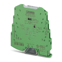
Identification of physical components and their numbering.

Block Diagram

Visual representation of signal flow and device connections.

Power Supply

Details methods and requirements for powering the device.

Assembly

Step-by-step instructions for mounting the module on a DIN rail.

Connecting the Wires

Procedures for securely connecting input and output signal wires.

Configuration

Configuration Table

Maps DIP switch settings to input and output signal ranges.

Adjustment

Connection/Application Example

Related product manuals