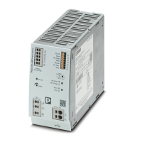
Do you have a question about the Phoenix Contact TRIO-UPS-2G/1AC/24DC/10 and is the answer not in the manual?
| Brand | Phoenix Contact |
|---|---|
| Model | TRIO-UPS-2G/1AC/24DC/10 |
| Category | UPS |
| Language | English |
Lists key characteristics and capabilities of the uninterruptible power supply unit.
Provides a concise summary of the UPS's key technical specifications for quick reference.
Details the uninterruptible power supply unit, its nominal capacity, and connection type.
Lists complementary products such as energy storage devices and cables for the UPS.
Covers input voltage ranges, current consumption, output voltage, and current for mains and battery operation.
Details connection methods, conductor cross-sections, and stripping lengths for input and output.
Describes battery technology, capacity, voltage, and connection details for battery output.
Explains signal outputs for DC OK, Alarm, Battery Mode, and Ready status via LEDs and transistor outputs.
Details signal connection data, remote control inputs, battery-operated start inputs, and interface specifications.
Covers power consumption, overvoltage category, efficiency, MTBF, protection class, and physical dimensions.
Specifies operating and storage temperatures, humidity, pollution degree, vibration, shock, and relevant standards.
Lists the certifications and approvals obtained by the uninterruptible power supply.
Details noise emission standards and requirements for residential, commercial, and industrial environments.
Covers immunity to electrostatic discharge, HF fields, fast transients, surge voltage, and conducted interference.
Explains the meaning of safety alert symbols, warning labels, and informational notes used in the document.
Provides critical safety instructions regarding electric shock, hot surfaces, and proper handling during installation.
Emphasizes observing national regulations, using appropriate enclosures, and ensuring proper convection for safe operation.
Identifies and labels the various functional components and connection terminals on the UPS device.
Displays the physical dimensions of the UPS and required clearance zones for installation.
Illustrates the internal functional blocks and signal flow of the UPS unit.
Guides on ensuring proper airflow for cooling and the standard DIN rail mounting orientation.
Step-by-step instructions for securely attaching the UPS device to a DIN rail.
Explains how to detach the UPS from the DIN rail and details procedures for rotated installation.
Describes how to use a wall adapter for mounting the UPS in environments with strong vibrations.
Details the tool-free push-in connection method for wiring and how to release cables.
Provides recommended conductor cross-sections and stripping lengths for input, output, and signal connections.
Explains AC input connection and the necessary protection measures for the primary side.
Illustrates connection diagrams for different network types (TN-S, TN-C, TT, IT).
Covers DC output connections and protection against short circuits and overloads on the secondary side.
Details how to connect the 24V battery module to the UPS and important safety notes.
Explains the function of signal outputs (DC OK, Alarm, Bat-Mode, Ready) and inputs (Remote, Bat-Start).
Provides general guidance and warnings for installing individual UPS components.
Describes how to set operating modes like Buffer Period, PC Mode, and Service Mode using the rotary selector.
Explains how to set the buffer time and provides a diagram for buffer time vs. discharge current.
Details the chronological sequence of UPS functions in PC mode, including delay time and PC shutdown.
Explains how to switch the UPS to service mode for maintenance or specific operational needs.
Provides a detailed procedure for replacing the battery modules, including safety warnings.
Describes how to use the Remote signal terminal to suppress battery operation or perform PC shutdown.
Explains how the Remote signal triggers immediate PC shutdown in PC mode.
Details how to use the UPS-CONF software to configure parameters, monitor status, and manage settings.
Illustrates the U/I characteristic curve with dynamic boost for reliable high switch-on currents.
Explains the dynamic boost feature for providing extra power during temporary load increases.
Describes the function of the LED indicators for visual monitoring of the UPS status.
Details the signal terminals for monitoring and controlling the UPS, including their functions.
Provides a comprehensive table mapping LED states and switching outputs to UPS operational statuses.
Details the specific signal outputs like DC OK, Alarm, Bat-Mode, and Ready, and their meanings.
Explains the function of signal inputs such as Remote and Bat-Start for control and activation.
Describes the USB Mini type B interface for data transmission and communication with PCs.
Explains how ambient temperature affects the output current and power capacity of the UPS.
Details how installation height influences the UPS performance and potential derating.
Describes how to connect UPS units in parallel for increased redundancy and system reliability.
Explains how parallel connection can be used to increase the overall output power capacity of the UPS system.
 Loading...