12
EN
8
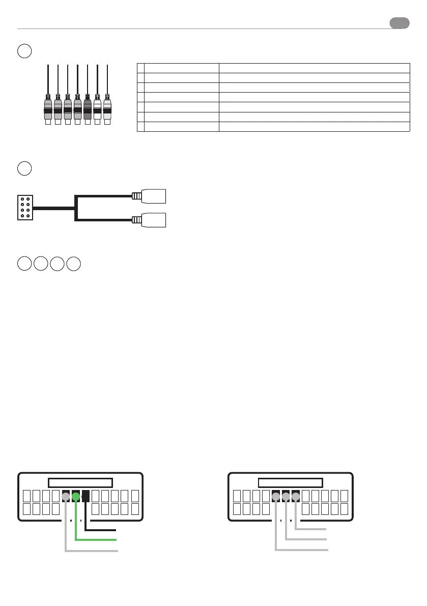
USB INPUTS
USB 1
USB 2
USB
USB
BLACK
GREEN-WHITE
GREY-WHITE
Resistive steering wheel control
For connections to the original car connector, use the diagrams provided in the interface instruction manual
04083. For cars with CAN line it is necessary to connect the CAN-BUS SWC interface.
CABLES
VM052
CABLES
04083
KEY 1 -> GREEN-WHITE
KEY 2 -> GREY-WHITE
KEY GND -> BLACK
Cable colour matching
Example
CONNECTION DIAGRAM IN INSTRUCTION MANUAL 04083 VM001 CONNECTION DIAGRAM
KEY GND
KEY 1
KEY 2
2
9
4
5
NOT ENABLED
7
DAB INPUT 2
A
CVBS OUT 1 Yellow - Output
B
CVBS OUT 2 Yellow - Output
C CAM CVBS
Yellow - Camera
D
AUX CVBS Yellow - Input
E AUX - R
Red - Input
F AUX - L
White-Input
G CAMERA PWR + 12V
Grey - Activated byconnecting the Back cable
A B C D E F G
Connections