Page 9 of 16
P F 3 2 M O D E S O F O P E R A T I O N
T C S P C M O D E
Often, TCSPC is thought of as a fast stopwatch – the start being the emission of the pulsed light
source and the stop being the detection of a single photon. However, like many TCSPC systems,
the PF32 performs reverse start-stop measurements: the detection of a single photon starts the
time-to-digital converter (TDC) and the next synchronisation pulse stops this process. This is
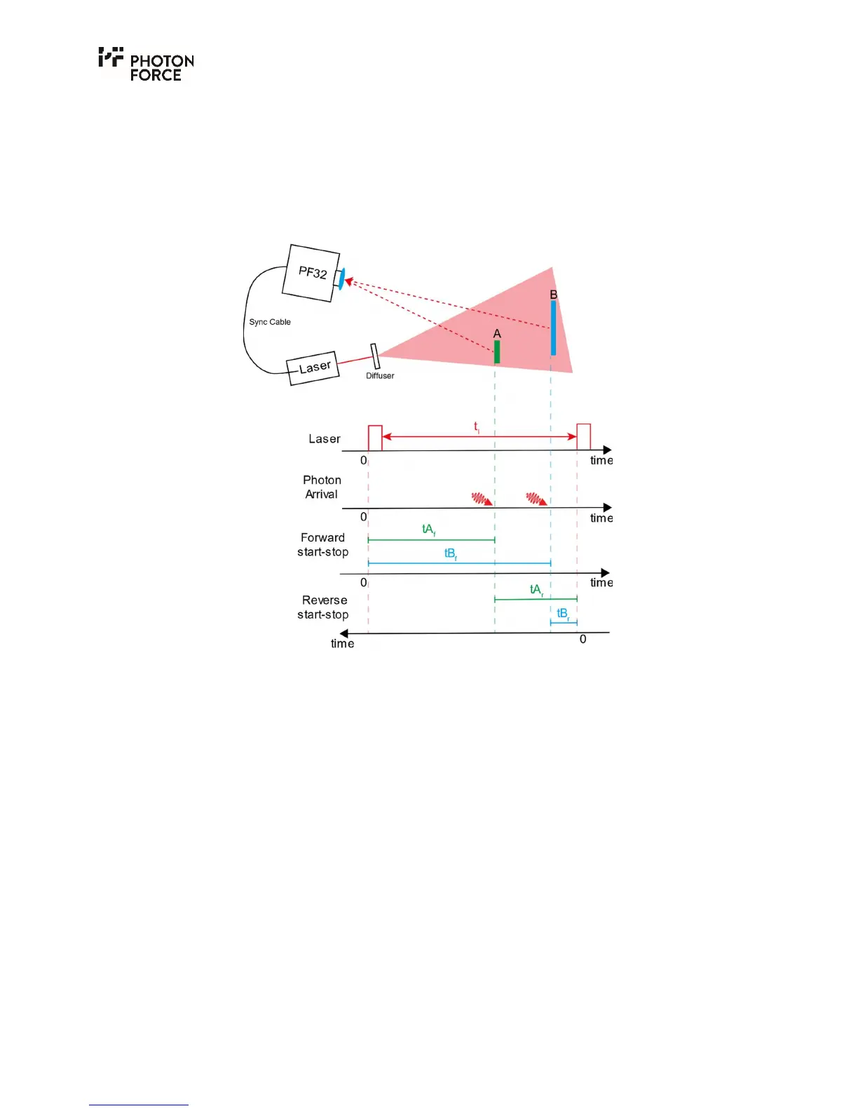
explained in the following diagram.
Using a basic laser-ranging setup as an example, the reverse start-stop principle can be explained.
A pulsed laser beam passes through a diffuser and illuminates 2 surfaces, A and B. Photons are
scattered from these surfaces and some will be collected by the PF32. Below the ranging setup we
show the timing of the processes involved (for simplicity, we consider a half round trip). The laser
period is t
l
, and at some time later, photons are detected by the PF32. Considering forward start-
stop, the time stamp given to a photon from surface A (tA
f
) has a lower value than that of a photon
from surface B (tB
f
). In reverse start-stop, the detection of a photon starts the timing process and
the timing information is given relative to the subsequent laser sync pulse. This results in the time
stamp for surface A (tA
r
) being of a greater value than that of surface B (tB
r
).
Reverse start-stop measurements are advantageous since they ensure that the counting
electronics are only active when a photon has been detected; in forward start-stop, the
synchronisation signal starts the timing and the detection of a photon stops the timing. This
means that the timing electronics are in constant use and need to be reset every synchronisation
period, potentially increasing readout dead time, power consumption, and heat dissipated
through the device.
The PF32 can accept a synchronisation signal via the Sync SMA connector (3.3V max as set out in
the synchronization document) in laser-is-master mode. Alternatively, the FPGA within the
camera can be used to provide the synchronisation signal to the TDC and also output this to the
light source via the TRIG SMA connection (0 to 3.3V).



 To Next Page